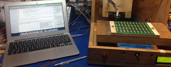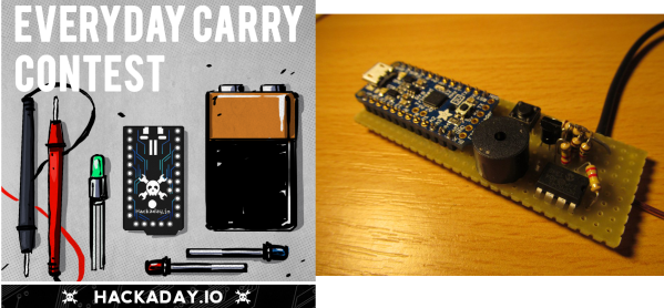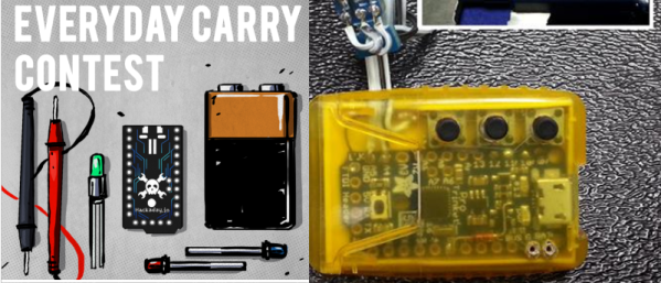
[Lou]’s entry for the Trinket EDC Contest is a great addition to the ubiquitous digital calipers found on workbenches and eBay resellers the world over. It translates the value displayed on the calipers to a USB HID interface for logging all those tricky measurements at the push of a button.
Most of the digital calipers you’ll find at Harbor Freight or on eBay are pretty much the same. There are two pads on the caliper’s PCB that give any microcontroller the ability to read what is being measured. It’s done with a 24-bit encoding scheme, where each bit is a nearly-BCD measurement in units of 1/1000 of an inch or 1/100 of a millimeter. After decoding the value, [Lou]’s trinket sends a few numbers to a computer over a USB HID interface.
Simply sending a measurement to a computer over USB wasn’t enough for [Lou]. He added three buttons to the project for typing multiple characters. The first button just sends Enter to the computer, the second sends a comma, and the third sends “/2 (Enter)”, exactly what you need to input the radius of something when measuring the diameter.
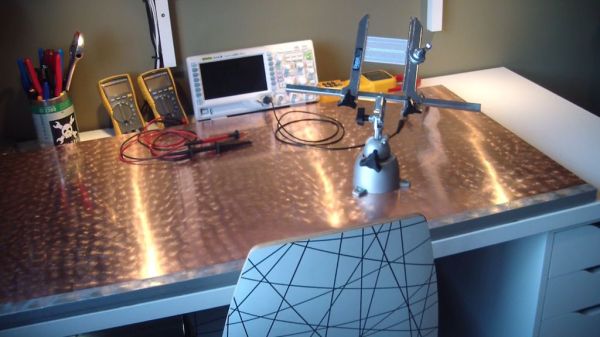
This was a project for the Trinket EDC Contest that ended a few hours ago. Nobody knows who the winner is, but there are some pretty cool prizes up for grabs including the new Rigol scope, a Fluke 179, and a soldering station.