Oscilloscope Thinks It’s A Video Monitor

There is nothing wrong with your television set. Do not attempt to adjust the picture.

Where would we be if we listened to advice like that? [Eric] writes that with a fairly simple circuit, he’s able to split a composite video signal into its constituent X and Y ramp signals for display on his trusty Tektronix 465m. A LM1881 IC does the bulk of the heavy lifting. After running the signal through a few passive components, the generated ramp signals are ready for consumption by his venerable ‘scope. All that’s needed past that is some additional glue logic to invert the levels so the image shows up properly. The end result is a display that has an almost ethereal quality to it, like an old TV set or something out of the movie Brazil.

Hit the break to catch a video of the circuit in action.

Continue reading “Oscilloscope Thinks It’s A Video Monitor”

Propeller Proto Board Has You Flying In No Time

propeller_proto_board

[Parker] was in need of a Propeller development board to make working on his projects easier. More often than not, when he needed to prototype something, he would pull the only one he had on hand from his home made pinball machine, and replace it when finished. This was time consuming and cumbersome, so he decided he needed a better way of doing things.

He looked into purchasing a Gadget Gangster proto board which allows you to use a Propeller much like an Arduino, complete with support for shields and the like. Unfortunately, they were sold out and he was in a hurry to finish up a project. Rather than wait, he decided to build his own proto board, which would be more flexible than the COTS version – allowing him to add things like an Analog to Digital converter without having to use a shield.

He looked around online and found some schematics to follow, and had his proto board constructed in no time. It gets the job done and looks quite clean, considering it was put together using perf board.

Keep reading to see a video walkthrough of the Propeller development board construction.

Continue reading “Propeller Proto Board Has You Flying In No Time”

Portable Bench Supply Carries Around 10 Amp-hours Of Juice

[Punish3r] wanted to have power for prototyping on the go. What he came up with is this little thing above. Inside you’ll find common components that let the unit provide 10 amp hours of current with a 12V 500mA output.

The storage capacity is provided by a dozen Lithium batteries. These 3.7V cheapies are wired in parallel behind a protection board. For charging and discharging, a Sparkfun LiPo charger board was used, taking care of all the work necessary to top off the batteries using a wall-wort. The final piece in the puzzle is a boost converter that provides the regulated 12v connected to the red and black banana plug receivers on the bottom of the case.

This is very much a plug-and-play design… just make sure you hook the parts up correctly and you’re up and running. We would love to see a roll-your-own boost converter circuit that include a switch or dial that lets you select common PSU voltage levels. If you’re going to the trouble to make your own board you might as well incorporate the charging circuit at the same time.

[Thanks Paul]

Function Generator Built And Mounted Inside Electronics Bench

A function generator is a handy piece of test equipment to have on-site. [Kammenos] designed and built his own function generator, using the bench itself as the enclosure. You can see above that the control panel presents a clean finished look. To achieve it, [Kammenos] designed and printed the panel labels on a sheet of paper, and used a piece of acrylic to protect it. The circuit inside uses a MAX038 high-frequency generator chip. This is a full-featured part that allows for great control based on a few external components. One of those is a selectable frequency range based on the capacitance value on one pin. This is selectable using a twelve-step rotary switch with a dozen different cap values. There’s also adjustment knobs for fine tuning, duty cycle, and DC offset.

Check out the video after the break for a full demonstration. If you want to build this yourself you’ll need to do some chip hunting. The MAX038 is obsolete. You may still be able to find one, but at around $20 you should be able to source a replacement with the same features and save yourself cash all in one step.

Continue reading “Function Generator Built And Mounted Inside Electronics Bench”

Multi-Function Bench Power Supply

Concerned with your project’s power consumption but don’t want to constantly leave an ammeter wired in series with your power supply? [Rajendra] feels your pain and has recently documented his solution to the problem: a variable-output bench top power supply that clearly displays load current consumption among other things!

Everything is wired up in a nice roomy enclosure that has front-panel access to ±5V and variable outputs, an adjustment potentiometer, and even an input for an integrated frequency counter. A PIC16F689 MCU runs the show and displays the variable output voltage and current on a 16×2 character LCD. Although clearly useful as is, the PIC has plenty of I/Os and muscle left for future expansion and a capacitance meter has already been hinted at as and addition for version 2!

Continue reading “Multi-Function Bench Power Supply”

DIY Scanning Electron Microscope

[Ben Krasnow]  has recently completed a home-built scanning electron microscope and has posted a video of it in action on his blog.

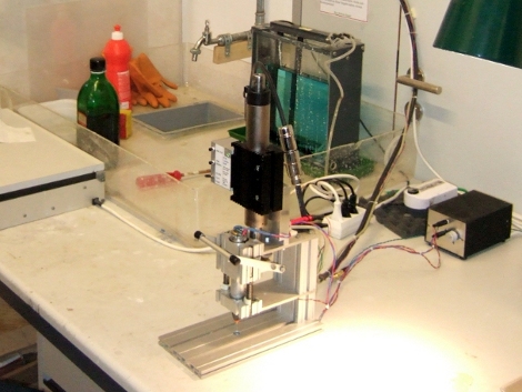
The build itself was done quite creatively using many off-the shelf components. We particularly like how long threaded brass rods were used not only for the supports, but also to maintain column alignment and fine-tune the spacing between the various beam focusing components.  A large glass “bell jar” covers the entire apparatus and is sealed to the bottom plate when the air is removed from within by a mechanical vacuum pump.

In order to produce an image, an electron gun similar to one found in a conventional CRT television tube accelerates the electrons with a 5kV potential from the top of the microscope downwards through a long copper column. Along the way the beam is focused and manipulated by electronic lenses in much the same way that light would be handled by conventional optical lenses. Near the base of the main column there are electrostatic deflection plates placed orthogonally in the X and Y directions that allow for precise scanning of the beam across the sample’s surface. When this high-energy electron beam is scanned across the sample, scattering surface electrons are then picked up by a nearby detector consisting of a phosphor screen and photomultiplier – a system that supposedly allows for higher sensitivity than trying to measure the small numbers of electrons directly.

Although the resolution of the first few scans is only around 50uM, this early success clearly shows that the device functions as intended and will provide a great starting point for future refinement with the final goal being resolutions down to the 1uM range.

Despite Ben’s reassurance that the x-rays produced at this energy level  won’t even penetrate the glass chamber, you can be sure that if we ever visit his garage we will definitely be donning some tin foil protection like these guys.

[Thanks kyle]

Continue reading “DIY Scanning Electron Microscope”

More Radiation Test Gear

This is a multifunction too for measuring radiation (translated). The measurements center around gas discharge tubes that react when ionizing particles pass through them. After reading about the counting circuit for the pair of tubes used in this handheld it’s easy to understand why these are tricky to calibrate. The handheld features a real-time clock as well as a GPS module. This way, it can not only give a readout of the radiation currently measured, but can record how much radiation exposure has accumulated over time (making this a dosimeter). An accompanying dataset records the location of the exposure. An ATmega128 drives the device, which is composed of two separate boards, a series of five navigation buttons, and a salvaged cellphone LCD for the readout. The translated page can be a bit hard to read at times, but there’s plenty of information including an abundance of schematic breakdowns with accompanying explanations of each.

This is certainly feature-rich and we think it goes way beyond the type of device that Seeed is trying to develop.

[Thanks Andrew]