Most wireless OEM hardware traditionally use 433MHz OOK modules to exchange information. The encoding and encryption of this data stream is left as a task for the embedded software designer. In most cases, the system can be hacked using a replay attack where an RF packet is recorded and replayed to emulate a valid user. [Gilad Fride] hacked his parking gate using this technique but decided to go the extra mile of connecting it to the internet.
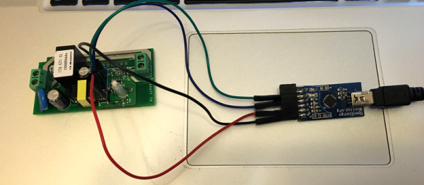
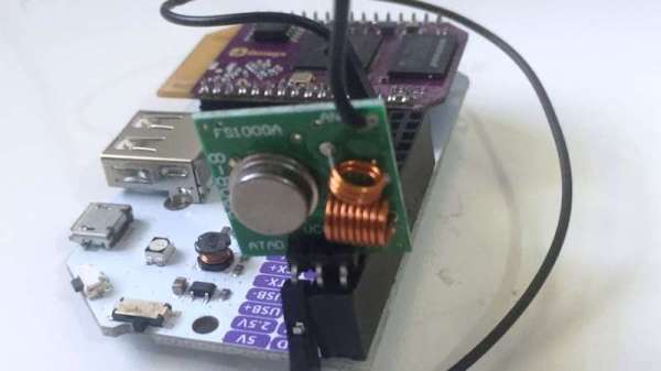
He used an RTL-SDR dongle and ook-decoder by [jimstudt] to sniff out the gate code and this code was tested using an Arduino. The final implementation was done around an Onion Omega which talks directly to the RF transmitter module using the fast-gpio binary. Internet connectivity was achieved using Onion Cloud API which is used to trigger the execution of code thereby sending the gate opening signal.
[Gilad Fride] uses the IFTTT Do button to provide a GUI and he demonstrates this in action using an iPhone in the video below. The project can be extended to open garage doors or turn off the lights of your room over the internet.
If you are looking to hack your home security system, look no further as SDRs have be used to communicate with wireless products effectively in the past. We are hoping manufacturers take a hint and start using better encryption. Continue reading “SDR Sniffing Electric Gates”