Test Your Signal With The WiFi Cup

[CNLohr] wanted to test the WiFi range in his house. One look at his roommate’s cup and an unorthodox idea was born. The WiFi Cup used an ESP8266 to connect to his home network. For output, [CNLohr] also added a WS2812 LED strip to the cup. The ESP8266 was programmed to send UDP packets to [CNLohr’s] laptop. When the laptop responded back, the ESP8266 turned on the LEDs, lighting up the cup. The cup’s response to signal strength was very quick – about a second.

[CNLohr] took the WiFi Cup around the house. He was surprised to detect the connection in corners he didn’t expect; in fact, the signal wasn’t weakening at all! He proceeded to walk outside with it, hoping to see the signal strength decrease. As a testament to his roommate’s robust router, the cup merely flickered. Hoping for a better test, [CNLohr] switched out the router for a cheaper TP-Link with shorter antennas. While the initial ping test showed a slower response time, the cup detected WiFi around the house just fine. It only wavered for a couple of moments when it was placed inside a metal bucket. We have to wonder how thin [CNLohr’s] walls are. WiFi never works that well in our house!

Continue reading “Test Your Signal With The WiFi Cup”

RFToy Makes Wireless Projects Easier

[Ray] has created RFToy, a simple gadget to aid in setting up wireless systems with a variety of common radio modules. RFToy is an open source microcontroller board running on an ATmega328. While RFToy is Arduino code compatible, [Ray] chose to ditch the familiar Arduino shield layout for one that makes it easier to install RF modules, and is more handheld friendly.

[RFToy] includes headers for the popular nRF24L01 2.4 GHz transceiver, as well as 433/315 transmitters and receivers found in many low-cost wireless electronic devices. The 128×64 pixel OLED screen and 3 button interface make it easy to set up simple user interfaces for testing new designs.

[Ray] hasn’t broken any new ground here. What he has done is create a simple tool for wireless projects. Anyone who’s worked on a wireless system can tell you that tools like this are invaluable for debugging why your circuit isn’t talking. Is it the transmitter? The receiver? Something else in the power supply circuit?

Check out [Ray’s] demo video after the break. In it, he sniffs, records, and plays back signals from several remote-controlled outlets. [Ray] also has a great demo of sending temperature data back and forth using an nRF24L01.

Continue reading “RFToy Makes Wireless Projects Easier”

Using Router SoCs As WiFi Modules (Yet Again)

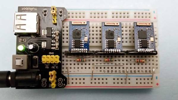
8-bit AVRs and 32-bit ARMs do one thing, and one thing well: controlling other electronics and sensors while sipping power. The Internet of Things is upon us and with that comes the need for connecting to WiFi networks. Already, a lot of chips are using repackaged System on Chips to provide an easy way to connect to WiFi, and the USR-WIFI232-T is the latest of the bunch. It’s yet another UART to WiFi bridge, and as [2XOD], it’s pretty easy to connect to an AVR.

The module in question can be had through the usual channels for about $11, shipped straight from China, and the only purpose of this device is to provide a bridge between a serial port and a wireless network. They’re not that powerful, and are only meant for simple tasks,

[2XOD] got his hands on one of these modules and tested them out. They’re actually somewhat interesting, with all the configuration happening over a webpage served from the device. Of course the standard AT commands are available for setting everything up, just like the ESP8266.

With a month of testing, [2XOD] has found this to be a very reliable device, logging temperatures every minute for two weeks. There’s also a breakout board available to make connection easy, and depending on what project you’re building, these could be a reasonable stand-in for some other popular UART -> WiFi chips.

Checking Email With The ESP8266

Ever so slowly, everyone’s favorite WiFi adapter is making its way into Internet-enabled projects. [jimeer01] created a device that reads the subject and sender lines from the latest email in his inbox and displays it on an LCD using the ESP8266 WiFi chip.

[jimeer] is using a ByPic for writing to the LCD and querying an inbox through an ESP8266 module. The ByPic is a board built around the BV_Basic firmware, stuffing a PIC microcontroller in an Arduino form factor and giving it a BASIC interpreter. Because this board isn’t ‘compile and flash’ like an Arduino, it’s perfectly suited for changing WiFi configurations and IMAP server credentials on the fly.

The device grabs the latest email in an inbox and displays the date, sender, and subject on the display. After scrolling through those lines, the PIC hits the ESP8266 to query the server again, grabbing the latest email, and repeating the whole process again, all without needing to connect the device to a computer. Video below.

Continue reading “Checking Email With The ESP8266”

An ESP8266 Based Smartmeter

During these last weeks we’ve been talking a lot about the ESP8266, a $4 microcontroller based Wifi module. As the SDK was recently released by Espressif a lot of cheap Internet of Things applications were made possible.

[Thomas] used one module to make a simple smartmeter measuring the active time of his heater together with the outside temperature. He added 2 AT commands starting/stopping the logging process and used one GPIO pin to monitor the heater’s oil pump state. The measurements are then periodically pushed via a TCP connection to his data collecting server, which allows him to generate nice graphs.

In the video embedded below you’ll see [Thomas] demoing his system. On his hackaday.io project page he put up a very detailed explanation on how to replicate his awesome project. All the resources he used and create can also be downloaded on the project’s GitHub page.

Continue reading “An ESP8266 Based Smartmeter”

Wireless Warning Sign

Bluetooth-Enabled Danger Sign For Lab

[A Raymond] had some free time at work, and decided to spend it on creating a wireless warning sign. According to his blog profile, he is a PhD student in Applied Physics. His lab utilizes a high-powered laser system. His job is to use said system, but only after it’s brought online by faculty scientists. The status of the laser system is changed by a manual switchbox that controls the warning signs wired around the lab entrances. Unfortunately, if you were in the upstairs office, you only knew this after running downstairs to check. [A Raymond’s] admitted laziness finally got the better of him – he wanted a sign that displayed the laser’s status from the comfort of the office. He had an old sign he could use, but he wanted a way for it to communicate with the switchbox downstairs. After some thought, he decided Bluetooth was the way to go, using a pair of BlueSMiRF Bluetooth modules from Sparkfun and Arduino Uno R3’s.

He constructed a metal box that intercepted the cable from the main switchbox, mounting one BlueSMiRF and Uno into it. Upon learning that the switchbox sends 12V AC signals over three individual status wires, he half-wave rectified the wires and divided their voltages so that the Uno wouldn’t fry. Instead, it determined which status wire that had active voltage. and sent a “g(reen)”, “y(ellow)”, or “r(ed)” signal continuously via Bluetooth. On the receiving end, [A Raymond] gutted the sign and mounted the other BlueSMiRF and Uno into it along with some green, yellow, and red LEDs. The LEDs light up in response to the corresponding Bluetooth signal.

The result is a warning sign that is always up-to-date with the switchbox’s status. We’ve covered projects using Bluetooth before, from plush birds to cameras– [A Raymond’s] wireless sign is in good company. He notes that it’s “missing” a high pitched whining noise when the “Danger” lights are on. If he decides to add an accompanying (annoying) sound, he couldn’t go wrong with something like this. Regardless, we’re sure [A Raymond] is happy that he no longer has to go back and forth between floors before he can use the laser.

Using A Standard Coil For NFC Tag Implant Reading

A few months ago Hackaday covered the xNT crowdfunding campaign which aimed at making an NTAG216 based NFC implant for different purposes. I actually backed it, found that standard NFC readers don’t perform well and therefore decided to try using a standard coil as an antenna for better reading performances.

Most NFC readers typically only have a small sweet spot where implant reading is possible. This is due to what we call coupling factor which depends on the reading distance and reader & NFC tag antenna geometries. Having a smaller antenna diameter increases the coupling factor and makes implant positioning easier.

In my detailed write-up you’ll find a good introduction to impedance matching, a process where a few passive components are added in series/parallel with an antenna to bring its complex impedance close to a RF signal transmitter’s. This usually requires expensive tools but allows optimal power transmission at a given frequency.

You may find our xNT coverage here.