It’s a story we’ve heard so many times over the years: breathless reporting of a new scientific breakthrough that will deliver limitless power, energy storage, or whichever other of humanity’s problems needs solving today. Sadly, they so often fail to make the jump into our daily lives because the reporting glosses over some exotic material that costs a fortune or because there’s a huge issue elsewhere in their makeup. There’s a story from MIT that might just be the real thing, though, as a team from that university claim to have made a viable supercapacitor from materials as simple as cement, carbon black, and a salt solution. Continue reading “MIT Cracks The Concrete Capacitor”→
If you’ve been building circuits for any length of time, you probably know you need decoupling capacitors to keep your circuits stable. But even though it’s a favorite technique of ours, just scattering some around your PCB and hoping for the best isn’t necessarily the best approach. If you want to dig deeper into the why and how of decoupling, check out [Stephen Fleeman’s] post on the topic.
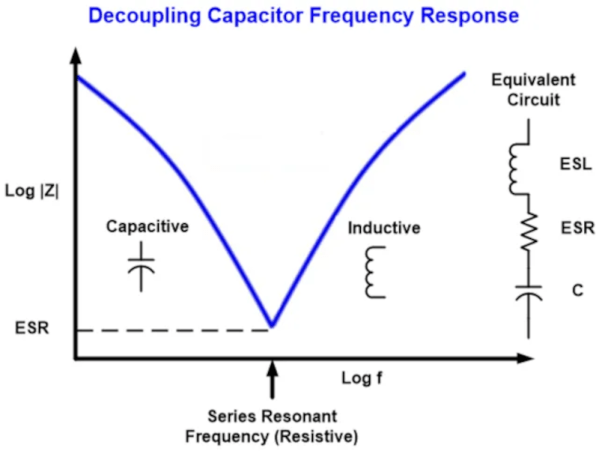
It is easy to think of capacitors as open circuits at DC and short circuits at high frequencies, shunting noise to ground. But the truth is more complex than that. Stray resistance and inductance mean that your simple decoupling capacitor will have a resonant frequency. This limits the high frequency protection so you often see multiple values used in parallel to respond to different frequencies.
Because the stray resistance and inductance plays a part, you may want to use fatter traces — less resistance — and shorter runs for less inductance. Of course, you can also use power and ground planes on the PCB as a form of decoupling. At the end of the post, [Stephen] talks a little about the importance of digital and analog ground that interact in a specific way.
If you want to do some empirical testing, you can build a test rig and do the work. Or check with [Bil Herd] about PCB inductance.
Solar panels are a great way to generate clean electricity, but require some energy storage mechanism if you also want to use their power at night. This can be a bit tricky for large solar farms that feed into the grid, which require enormous battery banks or pumped storage systems to capture a reasonable amount of energy. It’s much easier for small, handheld solar gadgets, which work just fine with a small rechargeable battery or even a big capacitor. [Jamie Matthews], for instance, built a loudspeaker that runs on solar power but can also work in the dark thanks to two supercapacitors.
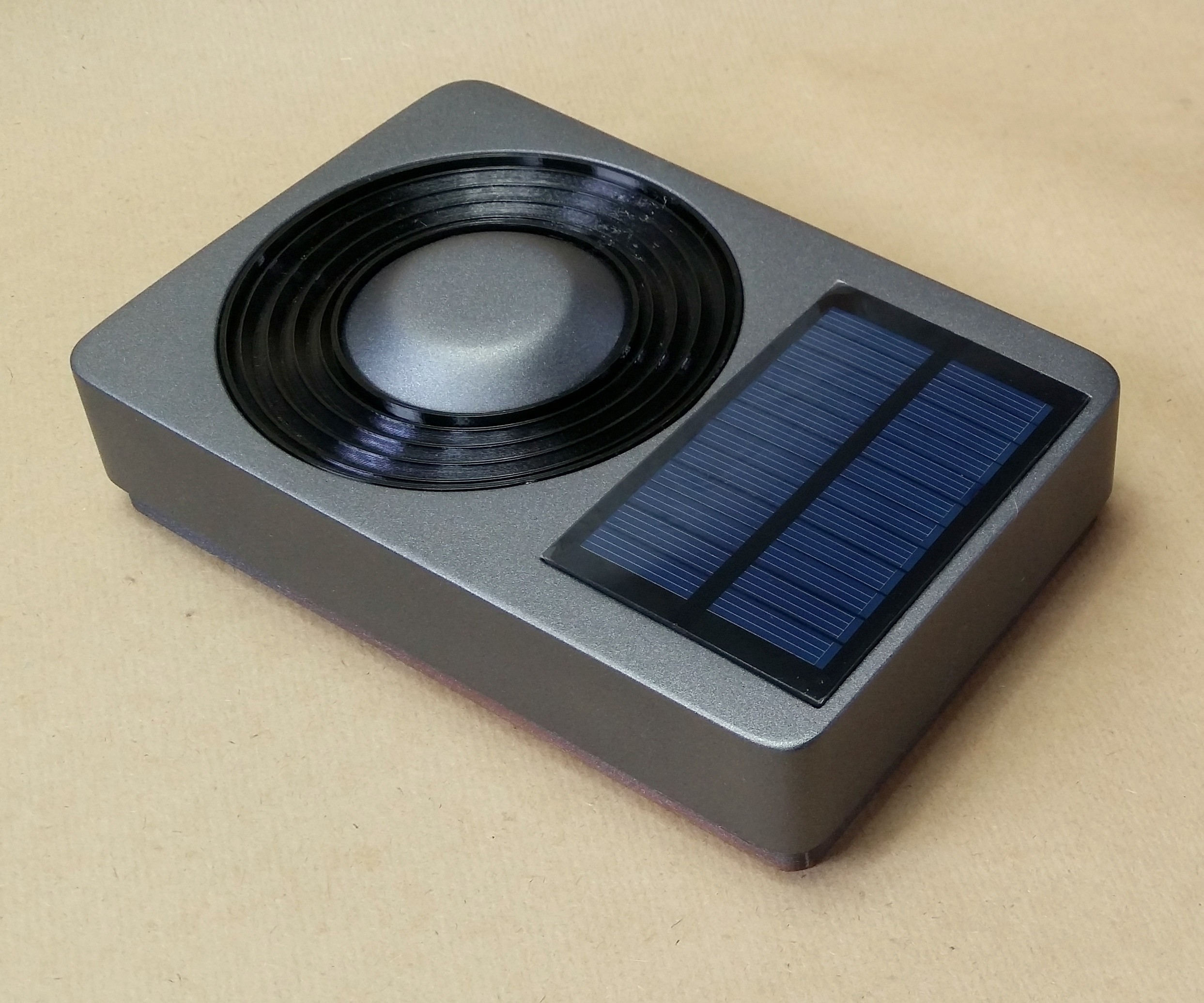
The speaker’s 3D-printed case has a 60 x 90 mm2 solar panel mounted at the front, which charges a pair of 400 Farad supercaps. Audio input is either through a classic 3.5 mm socket or through the analog audio feature of a USB-C socket. That same USB port can also be used to directly charge the supercaps when no sunlight is available, or to attach a Bluetooth audio receiver, which in that case will be powered by the speaker.
The solar panel sits right next to the passive radiator before both are covered with speaker fabric.
The speaker’s outer shell, the front bezel, and even the passive radiator are 3D-printed and spray-painted. The radiator is made of a center cap that is weighed down by a couple of M4 screws and suspended in a flexible membrane. [Jamie] used glue on all openings to ensure the box remains nearly airtight, which is required for the passive radiator to work properly. Speaker fabric is used to cover the front, including the solar panel – it’s apparently transparent enough to let a few watts of solar power through.
A salvaged three-inch Bose driver is the actual audio source. It’s driven by a TI TPA2013D1 chip, which is a 2.7 W class-D amplifier with an integrated boost converter. This enables the chip to keep a constant output power level across a wide supply voltage range – ideal for supercapacitor operation since supercaps don’t keep a constant voltage like lithium batteries do.
[Jamie] has used the speaker for more than nine months so far and has only had to charge it twice manually. It probably helps that he lives in sunny South Africa, but we’ve seen similar solar audio projects work just fine in places like Denmark. If you’re taking your boombox to the beach, a sunscreen reminder feature might also come in handy.
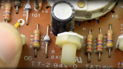
Having acquired some piece of old electronic equipment, be it a computer, radio, or some test gear, the temptation is there to plug it in as soon as you’ve lugged it into the ‘shop. Don’t be so hasty. Those power supplies and analog circuits often have a number of old aluminium electrolytic capacitors of unknown condition, and bad things can happen if they suddenly get powered back up again. After a visual inspection, to remove and replace any with obvious signs of leakage and corrosion, those remaining may still not be up to their job, with the oxide layers damaged over time when sat idle, they can exhibit lower than spec capacitance, voltage rating or even be a dead short circuit. [TechTangents] presents for us a guide to detecting and reforming these suspect capacitors to hopefully bring them, safely, back to service once more.
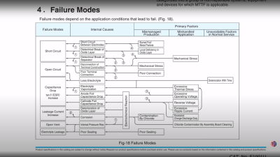
Capacitor failure modes are plentiful
When manufactured, the capacitors are slowly brought up to operating voltage, before final encapsulation, which allows the thin oxide layer to form on the anode contact plate, this is an electrically driven chemical process whereby a portion of the electrolyte is decomposed to provide the needed oxygen ions. When operating normally, with a DC bias applied to the plates, this oxidation process — referred to as ‘self-healing’ — continues slowly, maintaining the integrity of the oxide film, and slowly consuming the electrolyte, which will eventually run dry and be unable to sustain the insulating oxide layer.
If left to sit un-powered for too long, the anodic oxide layer will decay, resulting in reduced operating voltage. When powered up, the reforming process will restart, but this will be in an uncontrolled environment, resulting in a lot of excess heat and gases being vented. It all depends on how thin the oxide layer got and if holes have started to form. That is, if there is any electrolyte left to react – it may already be far too late to rescue.
If the oxide layer is sufficiently depleted, the capacitor will start to conduct, with a resultant self-heating and runaway thermal decomposition. They can explode violently, which is why there are score marks at the top of the can to act as a weak point, where the contents can burst through. A bit like that ‘egg’ scene in Aliens!
Yucky leaky capacitor. Replace these! and clean-up that conductive goo too.
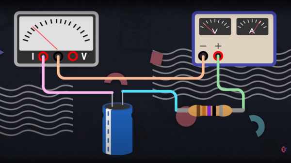
The ‘safe’ way to reform old capacitors is to physically remove them from the equipment, and apply a low, controlled voltage below the rated value to keep the bias current at a low value, perhaps just 2 mA. Slowly, the voltage can be increased to push the current back up to the initial forming level, so long as the current doesn’t go too high, and the temperature is within sensible bounds. The process ends when the applied voltage is at the rated value and the current has dropped off to low leakage values.
A word of warning though, as the ESR of the reformed caps could be a little higher than design, which will result in higher operating temperature and potentially increased ripple current in power supply applications.
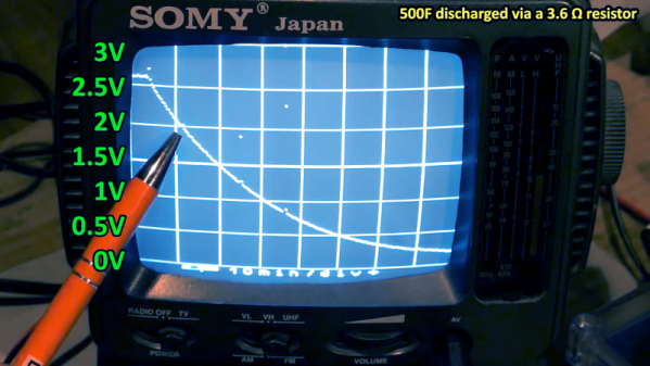
We’ve always been a little sad that supercapacitors aren’t marked with a big red S on a yellow background. Nevertheless, [DiodeGoneWild] picked up some large-value supercapacitors and used his interesting homemade oscilloscope to examine how they worked. You can watch what he is up to in his workshop in the video below.
Supercapacitors use special techniques to achieve very high capacitance values. For example, the first unit in the video is a 500 F capacitor. That’s not a typo — not microfarads or even millifarads — a full 500 Farads. With reasonable resistance, it can take a long time to charge 500F, so it is easier to see the behavior, especially with the homemade scope, which probably won’t pick up very fast signals.
For example, A 350 mA charging current takes about an hour to bring the capacitor up to 2.6 V, just under its maximum rating of 2.7 V. Supercapacitors usually have low voltage tolerance. Their high capacity makes them ideal for low-current backup applications where you might not want a rechargeable battery because of weight, heat, or problems with long-term capacity loss.
The real star of the video, though, is the cast of homemade test equipment, including the oscilloscope, a power supply, and a battery analyzer. To be fair, he also has some store-bought test gear, too, and the results seem to match well.
Supercapacitors are one of those things that you don’t need until you do. If you haven’t had a chance to play with them, check out the video or at least watch it to enjoy the homebrew gear. We usually look to [Andreas Spiess] for ESP32 advice, but he knows about supercaps, too. If you really like making as much as you can, you can make your own supercapacitors.
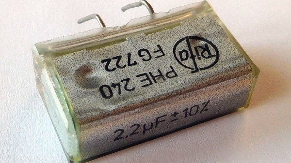
Anyone who works with older electronic equipment will before long learn to spot Rifa capacitors, a distinctive yellow-translucent component often used in mains filters, that is notorious for failures. It’s commonly thought to be due to their absorbing water, but based upon [Jerry Walker]’s long experience, he’s not so sure about that. Thus he’s taken a large stock of the parts and subjected them to tests in order to get to the bottom of the Rifa question once and for all.
What he was able to gather both from the parts he removed from older equipment and by applying AC and DC voltages to test capacitors, was that those which had been used in DC applications had a much lower likelihood of exhibiting precursors to failure, and also a much longer time before failure when connected to AC mains.
Indeed, it’s only at the end of the video that he reveals one of the parts in front of him is an ex-DC part that’s been hooked up to the mains all the time without blowing up. It’s likely then that these capacitors didn’t perform tot heir spec only when used in AC applications. He still recommends replacing them wherever they are found and we’d completely agree with him, but it’s fascinating to have some light shed on these notorious parts.
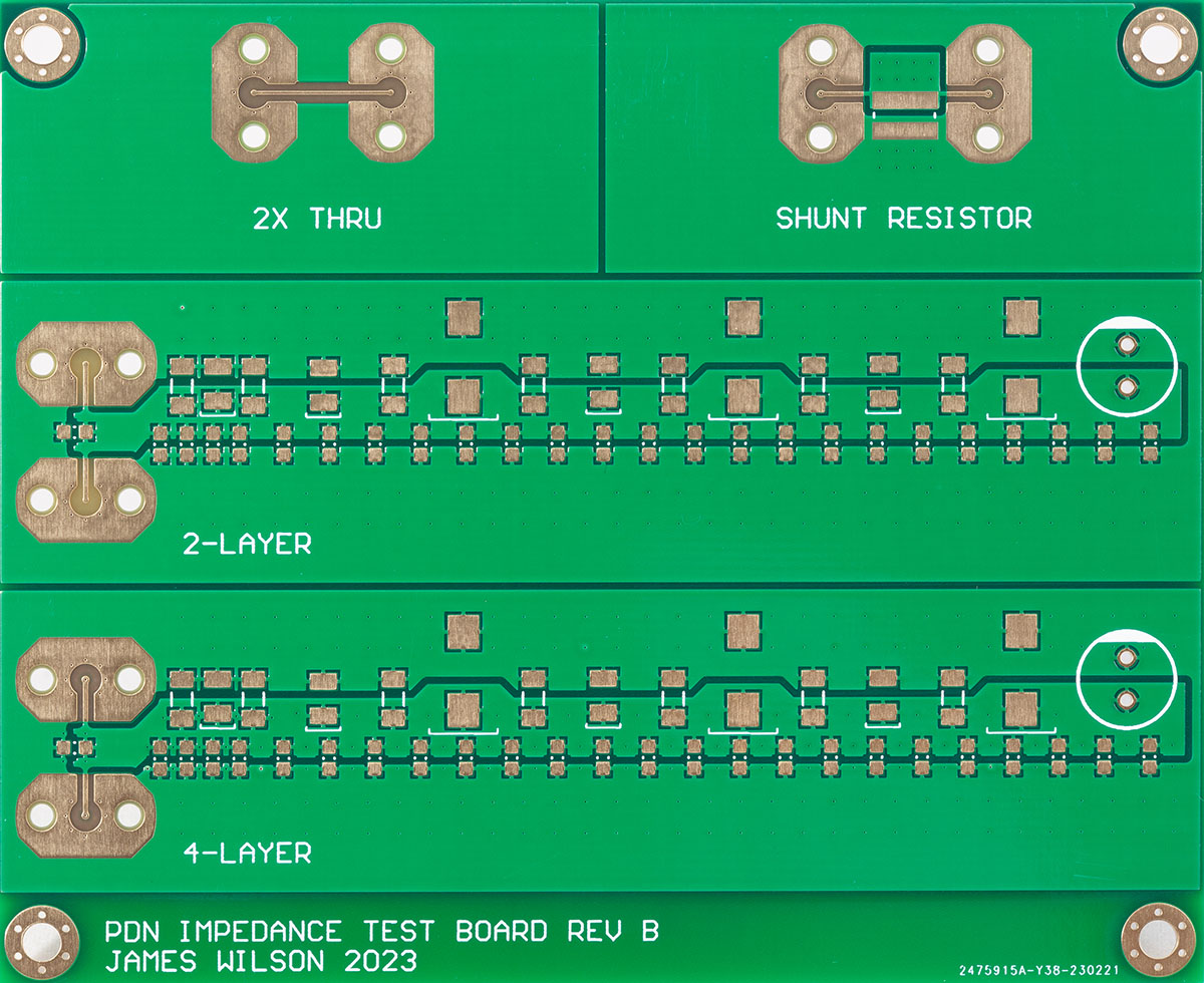
If you’ve done any amount of electronic design work, you’ll be familiar with the need for decoupling capacitors. Sometimes a chip’s datasheet will tell you exactly what kind of caps to place where, but quite often you’ll have to rely on experience and rules of thumb. For example, you might have heard that you should put 100 µF across the power supply pins and 100 nF close to each chip. But how close is “close”? And can that bigger cap really sit anywhere? [James Wilson] has been doing research to get some firm answers to those questions, and wrote down his findings in a fascinating blog post.
The test board has two-layer and four-layer sections. The inter-layer capacitance greatly affects the PDN’s performance in each case.
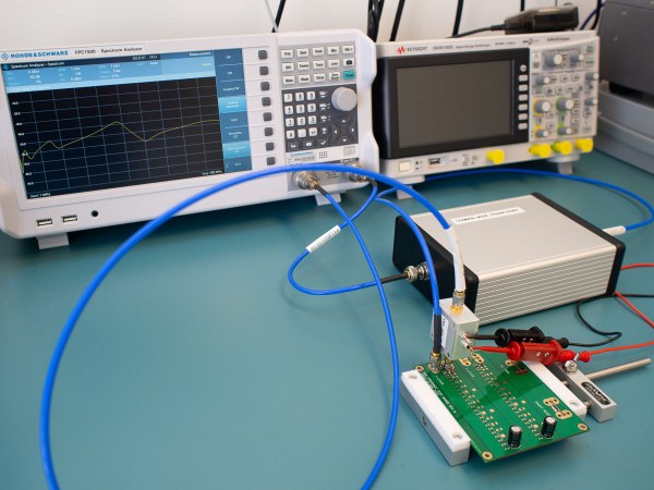
[James] designed a set of circuit boards that enabled him to place different types of capacitors at various distances along a set of PCB traces. By measuring the impedance of such a power distribution network (PDN) across frequency, he could then calculate its performance under different circumstances.
The ideal tool for those measurements would have been a vector network analyzer (VNA), but because [James] didn’t have such an instrument, he made a slightly simpler setup using a spectrum analyzer with a tracking generator. This can only measure the impedance’s magnitude, without any phase information, but that should be good enough for basic PDN characterization.
The results of [James]’s tests are pretty interesting, if not too surprising. For example, those 100 nF capacitors really ought to be placed within 10 mm of your chip if it’s operating at 100 MHz, but you can get away with even 10 cm if no signals go much above 1 MHz. A bulk 100 µF cap can be placed at 10 cm without much penalty in either case. Combining several capacitors of increasing size to get a low impedance across frequency is a good idea in principle, but you need to design the network carefully to avoid resonances between the various components. This is where a not-too-low equivalent series resistance (ESR) is actually a good thing, because it helps to dampen those resonances.
Overall, [James]’s blog post is a good primer on the topic, and gives a bit of much-needed context to those rules of thumb. If you want to dive deeper into the details of PDN design or the inductance of PCB traces, our own [Bil Herd] has made some excellent videos on those topics.