Gardening With…OpenSCAD?

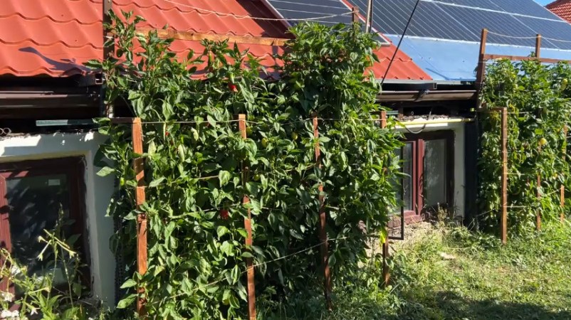
Unless it’s automated or using some other form of high-tech trickery, a vegetable garden isn’t exactly the sort of thing you’d expect to see on Hackaday. Be that as it may, the bountiful crop of peppers [Mihai Oltean] grew on the side of his house was done the old fashioned way, with nary a transistor in sight. So what’s the catch?

Well, in this case, it’s more about the journey than the end result. The produce sprouting in [Mihai]’s garden may be common enough, but the method in which he designed the garden itself is worth a closer look. To our knowledge, it’s the first time somebody sat down and wrote out all the code to generate a 3D model of a vertical garden in OpenSCAD.
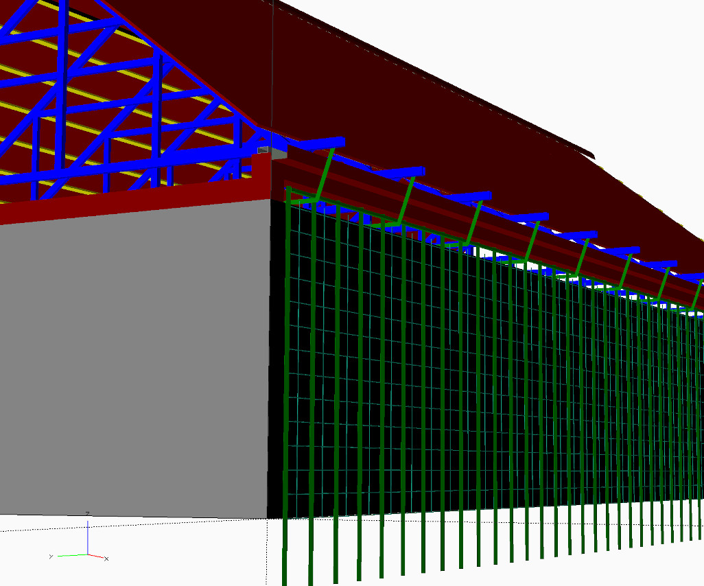
Usually, we see OpenSCAD used to produce design files for 3D printing or occasionally 2D CNC operations. But that’s not what’s happening here. The goal was to simply plan out how all the parts of the system would come together, and [Mihai] felt comfortable tackling it in the code-centric workflow offered by OpenSCAD. We know the feeling well.

Though the code isn’t necessarily being used to produce parts for manufacture, [Mihai] does bring in a bunch of virtual components to stand in for their corporeal counterparts. We’re partial to using a parts library such as NopSCADlib for this kind of thing, but from the looks of the GitHub repo, [Mihai] decided to implement his own versions of the screws, nuts, washers, and sections of metal extrusion used to construct the garden wall.

We recently covered the advantages of “building” a complex multi-part project like a CNC control cabinet virtually in your CAD tool of choice before bending metal on the real thing. This project is a fantastic example of that concept, as it shows that the technique isn’t limited to electronic components.
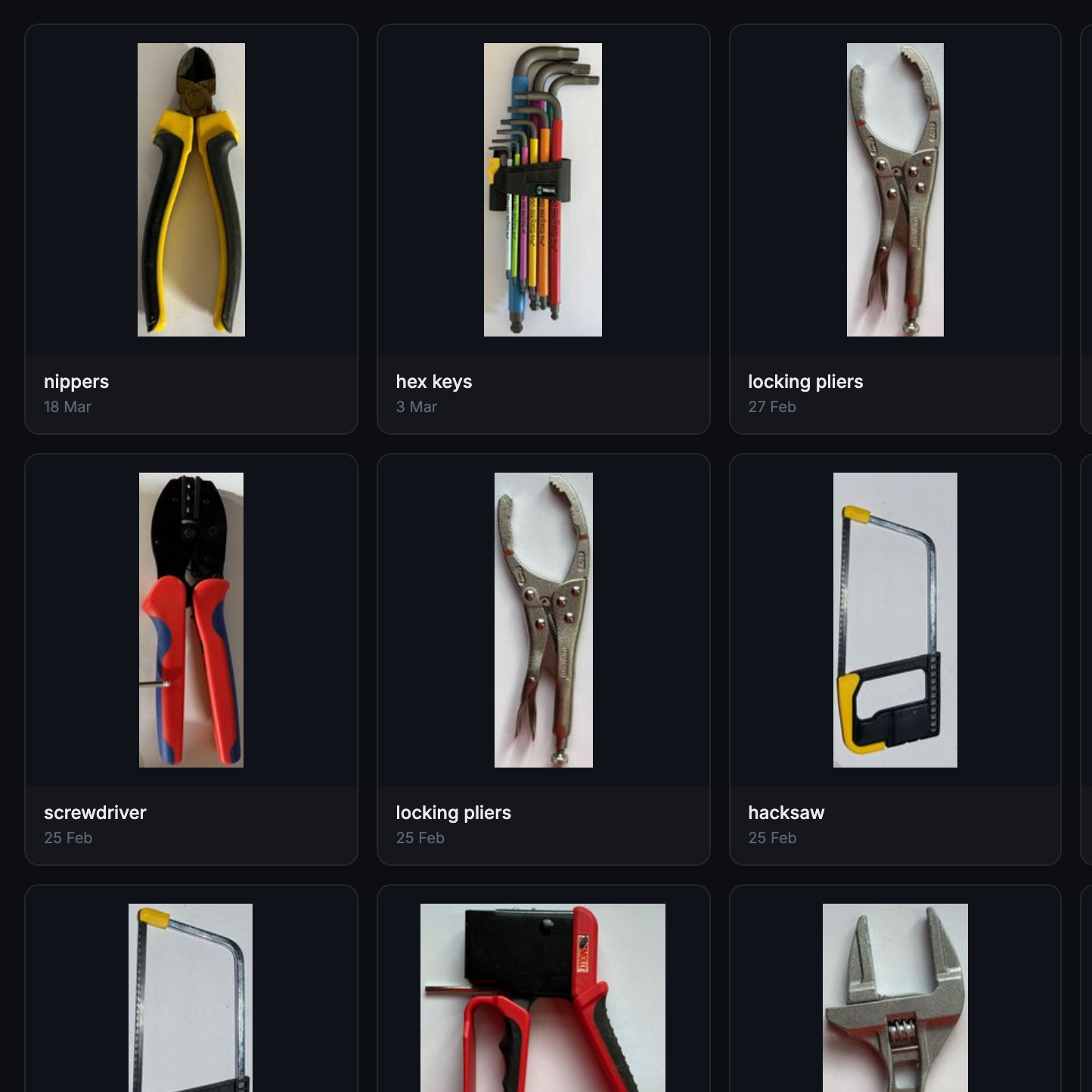
Take Tool Photo, Generate Custom Gridfinity Bin

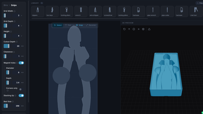
What if the organization and storage benefits of tool shadowing could be had and improved with a modular, semi-automated process? Tracefinity attempts that by generating custom Gridfinity bins from photos of tools, and has quite a few nifty features that are worth a look.

Maintaining a library of tools makes it easy to create project-based custom layouts.

The basic workflow is this: place one or more tools on a sheet of paper, take a photo, then upload the photo and have the system trace and save the outline and add it to a private tool library. When one is ready to create some bins, use the library of saved tool outlines to generate custom Gridfinity layouts.

If you’re unfamiliar, Gridfinity is a modular system of standardized bins and baseplates designed with 3D printing in mind, making it an ideal match for highly-customized organization tasks and a particularly natural fit for a tool-tracing system like this one.

The idea of taking a photo of a tool and generating a custom bin is a compelling one, and a couple years ago we covered a project that did just that. Tracefinity seems like a natural evolution of the idea, and includes handy features like easy design adjustments, optional magnet holes, and we really like the concept of a tool library from which individual tools are scanned once then later selected to create specific, project-based layouts.

Tracefinity takes advantage of new software capabilities like machine learning to improve and streamline the tracing process, but that doesn’t mean it relies on any external services. It can be entirely self-hosted and by default uses a local, CPU-friendly object detection model for tool tracing. There is an option to provide a API key to use Google Gemini instead, but it’s not required. It can come in handy for especially complex tool outlines or dealing with non-ideal source photos, however.

Noctua Releases 3D Models, But Please Don’t Try To Dupe The Products

Noctua wants to make life easier for fans of its…fans. To that end, the company has released a bevy of 3D models across its various product lines, all available to download for free.

If you’re not familiar with the company, Noctua specializes in high-quality cooling systems for the PC market. Its hope is that by freely providing 3D models of its components, it will aid aftermarket companies and DIYers that wish to integrate Noctua fans into their gear. In the company’s own words, these files are made available for “mechanical design, rendering, or animations.” They will let people check things like mountings and fitment without having to have the parts on hand, or to create demo visuals featuring the company’s products.

Don’t get too excited, though, because Noctua has already thought ahead. The company has specifically noted these parts aren’t intended for 3D printing, and critical components like fan blades have modified geometry so as to not compromise the companies IP. You could try and print these models, but they won’t perform like the real thing, and Noctua notes they shouldn’t be used for simulation purposes either. They’re intentionally not accurate to what the company actually sells in that regard.

That isn’t to say Noctua is totally against 3D printing. They have lots of parts available on Printables that they’d love you to try—everything from fan grilles to ducts to anti-vibration pads. Most are useful accessories—the kind of little bits of plastic that make using the products easier—that don’t threaten Noctua’s core product line in the marketplace.

If you’re whipping up a custom PC case and you want to kit it out with Noctua goodies, these models might help you refine your design. It’s funny how it’s such an opposite tactic to that taken by Honda, in terms of embracing the free exchange of 3D models on the open Internet. It’s a move that will surely be appreciated as a great convenience, and we’d love to see more companies follow this fine example.

Thanks to [irox] for the tip!

The Eleven-Faced Die That Emulates Two Six-sided Dice

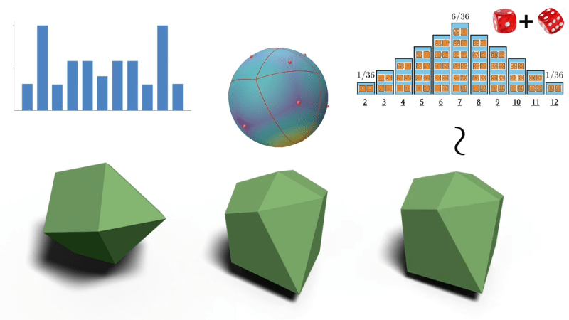
Rolling two six-sided dice (2d6) gives results from 2 to 12 with a bell curve distribution. Seven being the most common result, two and twelve being the least common. But what if one could do this with a single die?

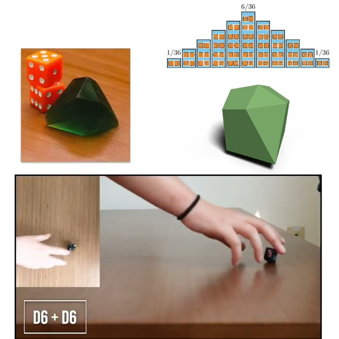
This eleven-sided die has a distribution matching the results of 2d6.

As part of research Putting Rigid Bodies to Rest, researchers show that a single eleven-sided asymmetric shape can deliver the same results. That is to say, it rolls numbers 2 to 12 in the same distribution as 2d6. It’s actually just one of the oddball dice [Hossein Baktash] and his group designed so if you find yourself intrigued, be sure to check out the 3D models and maybe print your own!

The research behind this is a novel method of figuring out what stable resting states exist for a given rigid body, without resorting to simulations. The method is differentiable, meaning it can be used not just to analyze shapes, but also to design shapes with specific properties.

For example, with a typical three-sided die each die face has an equal chance of coming up. But [Hossein] shows (at 8:05 in the video, embedded below) that it’s possible to design a three-sided die where the faces instead have a 25%-50%-25% distribution.

How well do they perform in practice? [Hossein] has done some physical testing showing results seem to match theory, at least when rolled on a hard surface. But we don’t think anyone has loaded these into an automated dice tester, yet.

Continue reading “The Eleven-Faced Die That Emulates Two Six-sided Dice” →

Make Fancy Resin Printer 3D Models FDM-Friendly

Do you like high-detail 3D models intended for resin printing, but wish you could more easily print them on a filament-based FDM printer? Good news, because [Jacob] of Painted4Combat shared a tool he created to make 3D models meant for resin printers — the kind popular with tabletop gamers — easier to port to FDM. It comes in the form of a Blender add-on called Resin2FDM. Intrigued, but wary of your own lack of experience with Blender? No problem, because he also made a video that walks you through the whole thing step-by-step.

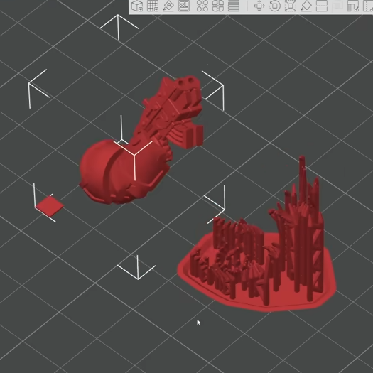
Resin2FDM separates the model from the support structure, then converts the support structure to be FDM-friendly.

3D models intended for resin printing aren’t actually any different, format-wise, from models intended for FDM printers. The differences all come down to the features of the model and how well the printer can execute them. Resin printing is very different from FDM, so printing a model on the “wrong” type of printer will often have disappointing results. Let’s look at why that is, to better understand what makes [Jacob]’s tool so useful.

Rafts and a forest of thin tree-like supports are common in resin printing. In the tabletop gaming scene, many models come pre-supported for convenience. A fair bit of work goes into optimizing the orientation of everything for best printed results, but the benefits don’t carry directly over to FDM.

For one thing, supports for resin prints are usually too small for an FDM printer to properly execute — they tend to be very thin and very tall, which is probably the least favorable shape for FDM printing. In addition, contact points where each support tapers down to a small point that connects to the model are especially troublesome; FDM slicer software will often simply consider those features too small to bother trying to print. Supports that work on a resin printer tend to be too small or too weak to be effective on FDM, even with a 0.2 mm nozzle.

To solve this, [Jacob]’s tool allows one to separate the model itself from the support structure. Once that is done, the tool further allows one to tweak the nest of supports, thickening them up just enough to successfully print on an FDM printer, while leaving the main model unchanged. The result is a support structure that prints well via FDM, allowing the model itself to come out nicely, with a minimum of alterations to the original.

Resin2FDM is available in two versions, the Lite version is free and an advanced version with more features is available to [Jacob]’s Patreon subscribers. The video (embedded below) covers everything from installation to use, and includes some general tips for best results. Check it out if you’re interested in how [Jacob] solved this problem, and keep it in mind for the next time you run across a pre-supported model intended for resin printing that you wish you could print with FDM.

Continue reading “Make Fancy Resin Printer 3D Models FDM-Friendly” →

Belfry OpenSCAD Library (BOSL2) Brings Useful Parts And Tools Aplenty

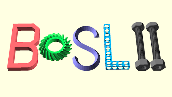
OpenSCAD has a lot of fans around these parts — if you’re unaware, it’s essentially a code-based way of designing 3D models. Instead of drawing them up in a CAD program, one writes a script that defines the required geometry. All that is made a little easier with the Belfry OpenSCAD Library (BOSL2).

Designing a part like this is a cinch with BOSL2.

BOSL2 has an extensive library of base shapes, advanced functions for manipulating models, and some really nifty tools for creating attachment points on parts and aligning components with one another. If that sounds handy for designing useful objects, you’re in for even more of a treat when you see their functions for gears, hinges, screws, and more.

There’s even one that covers bottle necks and caps. (Those are all standardized by the way, so it’s never been easier to interface to existing bottles or caps in a project.)

OpenSCAD really is very versatile software. It powers useful tools like this screw, washer, and nut generator as well as having more unusual applications like a procedural terrain generator. It’s free, so if you’ve never looked into it, check it out!

Watch A 3D Scan Become A Car Body Model

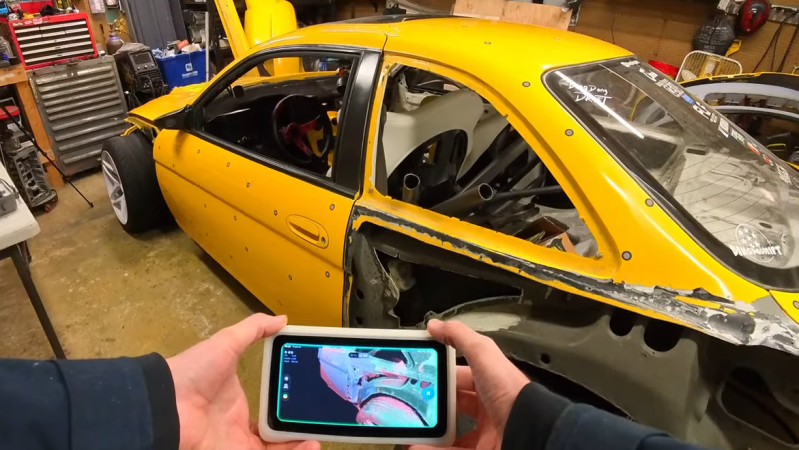
Not all 3D scanning is alike, and the right workflow can depend on the object involved. [Ding Dong Drift] demonstrates this in his 3D scan of a project car. His goal is to design custom attachments, and designing parts gets a lot easier with an accurate 3D model of the surface you want to stick them on. But it’s not as simple as just scanning the whole vehicle. His advice? Don’t try to use or edit the 3D scan directly as a model. Use it as a reference instead.

Rather than manipulate the 3D scan directly, a better approach is sometimes to use it as a modeling reference to fine-tune dimensions.

To do this, [Ding Dong Drift] scans the car’s back end and uses it as a reference for further CAD work. The 3D scan is essentially a big point cloud and the resulting model has a very high number of polygons. While it is dimensionally accurate, it’s also fragmented (the scanner only captures what it can see, after all) and not easy to work with in terms of part design.

In [Ding Dong Drift]’s case, he already has a 3D model of this particular car. He uses the 3D scan to fine-tune the model so that he can ensure it matches his actual car where it counts. That way, he’s confident that any parts he designs will fit perfectly.

3D scanning has a lot of value when parts have to fit other parts closely and there isn’t a flat surface or a right angle to be found. We saw how useful it was when photogrammetry was used to scan the interior of a van to help convert it to an off-grid camper. Things have gotten better since then, and handheld scanners that make dimensionally accurate scans are even more useful.

Continue reading “Watch A 3D Scan Become A Car Body Model” →