The war of the currents was fairly decisively won by AC. After all, whether you’ve got 110 V or 230 V coming out of your wall sockets, 50 Hz or 60 Hz, the whole world agrees that the frequency of oscillation should be strictly greater than zero. Technically, AC won out because of three intertwined facts. It was more economical to have a few big power plants rather than hundreds of thousands of tiny ones. This meant that power had to be transmitted over relatively long distances, which calls for higher voltages. And at the time, the AC transformer was the only way viable to step up and down voltages.

But that was then. We’re right now on the cusp of a power-generation revolution, at least if you believe the solar energy aficionados. And this means two things: local power that’s originally generated as DC. And that completely undoes two of the three factors in AC’s favor. (And efficient DC-DC converters kill the transformer.) No, we don’t think that there’s going to be a switch overnight, but we wouldn’t be surprised if it became more and more common to have two home electrical systems — one remote high-voltage AC provided by the utilities, and one locally generated low-voltage DC.
Why? Because most devices these days use low-voltage DC, with the notable exception of some big appliances. Batteries store DC. If more and more homes have some local DC generation capability, it stops making sense to convert the local DC to AC just to plug in a wall wart and convert it back to DC again. Hackaday’s [Jenny List] sidestepped a lot of this setup and went straight for the punchline in her article “Where’s my low-voltage DC wall socket?” and proposed a few solutions for the physical interconnects. But we’d like to back it up for a minute. When the low-voltage DC revolution comes, what voltage is it going to be?

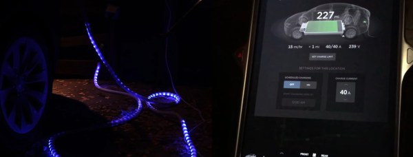
 The basic components behind the build are a current transformer, a NeoPixel LED strip, and an ATtiny44 to run the show. But the quality of the build is where [ch00f]’s project really shines. The writeup is top notch — [ch00f] goes to great lengths showing every detail of the build. The project log covers the challenges of finding appropriate wiring & enclosures for the high power AC build, how to interface the current-sense transformer to the microcontroller, and shares [ch00f]’s techniques for testing the fit of components to ensure the best chance of getting the build right the first time. If you’ve ever gotten a breadboarded prototype humming along sweetly, only to suffer as you try to cram all the pieces into a tiny plastic box, you’ll definitely pick something up here.