Switches seem to be the simplest of electrical components – just two pieces of metal that can be positioned to either touch each other or not. As such it would seem that it shouldn’t matter whether a switch is used for AC or DC. While that’s an easy and understandable assumption, it can also be a dangerous one, as this demo of AC and DC switching dramatically reveals.
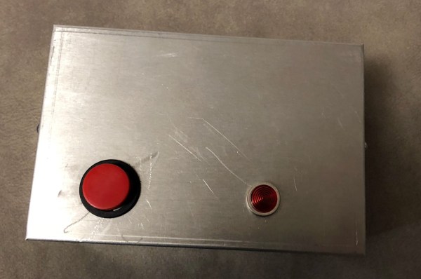
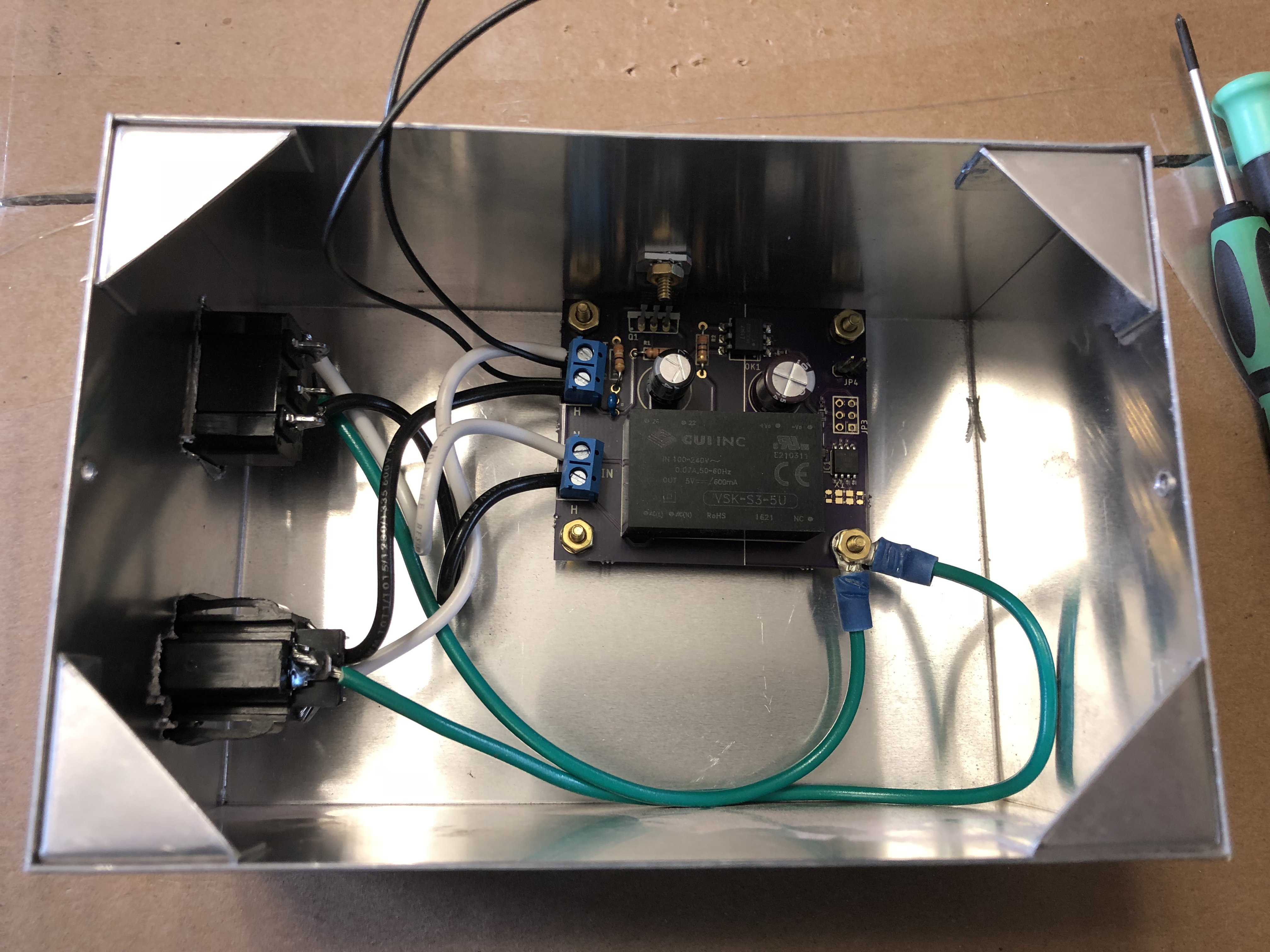
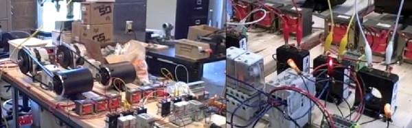
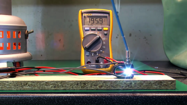
Using a very simple test setup, consisting of an electric heater for a load, a variac to control the voltage, and a homemade switch, [John Ward] walks us through the details of what happens when those contacts get together. With low-voltage AC, the switch contacts exhibit very little arcing, and even with the voltage cranked up all the way, little more than a brief spark can be seen on either make or break. Then [John] built a simple DC supply with a big rectifier and a couple of capacitors to smooth things out and went through the same tests. Even at a low DC voltage, the arc across the switch contacts was dramatic, particularly upon break. With the voltage cranked up to the full 240-volts of the UK mains, [John]’s switch was essentially a miniature arc welder, with predictable results as the plastic holding the contacts melted. Don your welding helmet and check out the video below.
As dramatic as the demo is, it doesn’t mean we won’t ever be seeing DC in the home. It just means that a little extra engineering is needed to make sure that all the components are up to snuff.
Continue reading “A Dramatic Demo Of AC Versus DC Switching”