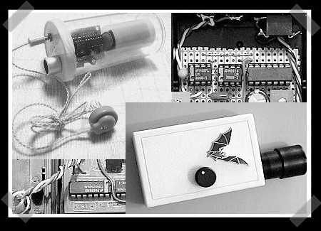
In 2012, [Bruno] wanted to detect some bats. Detect bats? Some varieties of bat (primarily the descriptively named “microbats”) locate themselves and their prey in space using echolocation, the same way your first robot probably did. The bat emits chirps from their adorably tiny larynx the same way a human uses its vocal cords to produce sound. The bat then listens for an echo of that sound and can make inferences about the location of its presumed prey in the volume around it. Bat detectors are devices which can detect these ultrasonic sounds and shift them into a range that humans can hear. So how would you build such a device? [Bruno]’s PicoBat probably sets the record for component count and code simplicity.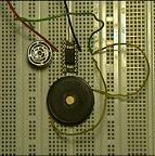
With no domain expertise the most conspicuous way to build a bat detector is probably to combine the glut of high performance microcontrollers with a similarly high performing analog to digital converter. With a little signal processing knowledge you sample the sounds at their native frequency, run them through a Fast Fourier transform, and look for energy in the ultrasonic frequency range, maybe about 20 kHz to 100 kHz, according to Wikipedia. With more knowledge about signal interference it turns out there are a surprisingly large number of ways to build such a device, including some which are purely analog. (Seriously, check out the Wikipedia page for the myriad ways this can be done.)
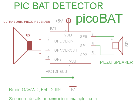 [Bruno] did use a microcontroller to build his bat detector, but not in the way we’d have expected. Instead of using a beastly high performance A/D and a similarly burly microcontroller, the PicoBat has a relatively tame PIC12 and a standard ultrasonic transducer, as well as a piezo buzzer for output. Along with a power rail, that’s the entire circuit. The code he’s running is similarly spartan. It configures a pair of GPIOs and toggles them, with no other logic. That’s it.
So how does this work? The ultrasonic transducer is designed mechanically to only receive sounds in the desired frequency range. Being piezoelectric, when enough sound pressure is applied the stress causes a small voltage. That voltage is fed into the PIC not as a GPIO but as a clock input. So the CPU only executes an instruction when ultrasonic sound with enough intensity hits the transducer. And the GPIO toggling routine takes four clock cycles to execute, yielding a 1:4 clock divider. And when the GPIOs toggle they flip the potential across the buzzer, causing it to make human-audible sound. Brilliant!
Check out [Bruno]’s video demo after the break to get a sense for how the device works. You might be able to do this same trick with other components, but we’re willing to be that you won’t beat the parts count.
Continue reading “PIC Powered PicoBat Picks Up Pulsed Power” →


