All About PNP Transistors

In the early days, PNP bipolar transistors were common, but the bulk of circuits you see today use NPN transistors. As [Aaron Danner] points out, many people think PNP transistors are “backward” but they have an important role to play in many circuits. He explains it all in a recent video you can see below.

He does explain why PNP transistors don’t perform as well as corresponding NPN transistors, but they are still necessary sometimes. Once you get used to it, they are no problem to handle at all. Common cases where you want a PNP are, for example, when you want to switch a voltage instead of a ground. There are also certain amplifier configurations that need PNP units.

Like an NPN transistor, a PNP can operate in saturation, linear operation, reverse active, or it can be cut off. [Aaron] shows you how to bias a transistor and you’ll see it isn’t much different from an NPN except the base-emitter diode junction is reversed.

As you might expect, current has to flow through that diode junction to turn the transistor on. The arrow points in the direction of the diode junction. If you want a refresher on transistor biasing, we got you. Sure, you don’t need to do it every day now, but it still is a useful skill to have.

Continue reading “All About PNP Transistors”

The Imperfect Bipolar Transistor

We like to pretend that our circuit elements are perfect because, honestly, it makes life easier and it often doesn’t matter much in practice. For a normal design, the fact that a foot of wire has a tiny bit of resistance or that our capacitor value might be off by 10% doesn’t make much difference. One place that we really bury our heads in the sand, though, is when we use bipolar transistors as switches. A perfect switch would have 0 volts across it when it is actuated. A real switch won’t quite get there, but it will be doggone close. But a bipolar transistor in saturation won’t be really all the way on. [The Offset Volt] looks at how a bipolar transistor switches and why the voltage across it at saturation is a few tenths of a volt. You can see the video below.

To understand it, you’ll need a little bit of math and some understanding of the construction of transistors. The idea of using a transistor as a switch is that the transistor is saturated — that is, increasing base current doesn’t make much change in the collector current. While it isn’t perfect, it is good enough to switch a relay or do other common switching tasks.

Continue reading “The Imperfect Bipolar Transistor”

Logic Chip Teardown From Early 1990s IBM ES/9000 Mainframe

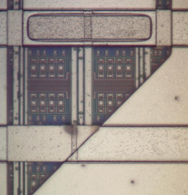
The 1980s and early 1990s were a bit of an odd time for semiconductor technology, with the various transistor technologies that had been used over the decades slowly making way for CMOS technology. The 1991-vintage IBM ES/9000 mainframe was one of the last systems to be built around bipolar transistor technology, with [Ken Shirriff] tearing into one of the processor modules (TCM) that made up one of these mainframes.

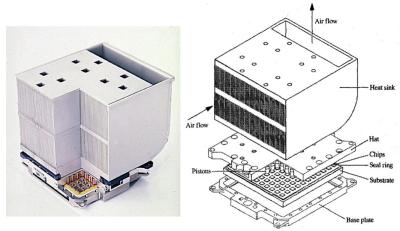
A Thermal Conduction Module from an IBM ES/9000 mainframe.

Five of these Thermal Conduction Modules (127.5 mm a side) made up the processor in these old mainframes. Most of note are the use of the aforementioned bipolar transistors and the use of DCS-based (differential current switch) logic. With the already power-hungry bipolar transistors driven to their limit in the ES/9000, and the use of rather massive DCS gates, each TCM was not only fed many amperes of electricity, but also capable of dissipating up to 600 Watts of power.

Each TCM didn’t contain a single large die of bipolar transistors either, but instead many smaller dies were bonded on a specially prepared ceramic layer in which the wiring was added through a very precise process. While an absolute marvel of engineering, the ES/9000 was essentially a flop, and by 1997 IBM too would move fully to CMOS transistor technology.

Over the years we’ve featured a lot of [Ken]’s work, perhaps you’d like to know more about his techniques.

Circuit VR: A Tale Of Two Transistors

Last time on Circuit VR, we looked at creating a very simple common emitter amplifier, but we didn’t talk about how to select the capacitor values, or much about why we wanted them. We are going to look at that this time, as well as how to use a second transistor in an emitter follower (or common collector) configuration to stiffen the amplifier’s ability to drive an output load.

Several readers wrote to point out that I’d pushed the Ic value a little high for a 2N2222. As it turns out, at least one of the calculations in the comments was a bit high. However, I’ve updated the post at the end to explore what was in the comments, and talk a bit more about how you compute power dissipation with or without LTSpice. If you read that post, you might want to jump back and pick up the update. Continue reading “Circuit VR: A Tale Of Two Transistors”

Circuit VR: Starting An Amplifier Design

Sometimes I wish FETs had become practical before bipolar transistors. A FET is a lot more like a tube and amplifies voltages. Bipolar transistors amplify current and that makes them a bit harder to use. Recently, [Jenny List] did a series on transistor amplifiers including the topic of this Circuit VR, the common emitter amplifier. [Jenny] talked about biasing. I’ll start with biasing too, but in the next installment, I want to talk about how to use capacitors in this design and how to blend two amplifiers together and why you’d want to do that.

But before you can dive into capacitors and cascades, we need a good feel for how to get the transistor biased to start with. As always, there’s good news and bad news. The bad news it that transistors vary quite a bit from device to device. The good news is that we’ll use some design tricks to keep that from being a problem and that will also give us a pretty wide tolerance on component values. The resulting amplifier won’t necessarily be precise, but it will be fine for most uses. As usual, you can find all the design files on GitHub, and we’ll be using the LT Spice simulator.

Continue reading “Circuit VR: Starting An Amplifier Design”