An Introduction To DC Boost Converters

simple_boost_converter

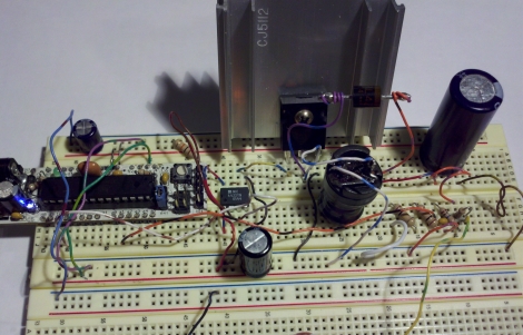
If you are planning on creating some sort of Nixie tube display, you will undoubtedly need to find yourself a high voltage DC power supply. If you don’t want to add a transformer to your project, you can always opt to build a boost converter instead. [Andrew Moser] shows us just how easy it is to build one, discussing the theory behind simple boost converters along the way.

Boost converters are often driven by dedicated ICs, but in this case the PWM signal from an Arduino does the job just fine. [Andrew] covers the process of choosing the proper components for the circuit, discussing duty cycles and components to avoid lest your boost converter die an untimely death.

He shows us how to implement a feedback system to get a more precise output voltage, but as Lady Ada has shown us, an open loop works pretty well too.

For the beginners that want to just get things up and running, his instructions and code should be sufficient, but [Andrew] provides plenty of reference links for those looking to delve deeper into the subject.

Portable Bench Supply Carries Around 10 Amp-hours Of Juice

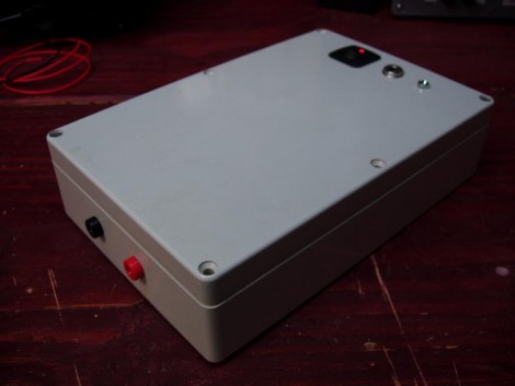
[Punish3r] wanted to have power for prototyping on the go. What he came up with is this little thing above. Inside you’ll find common components that let the unit provide 10 amp hours of current with a 12V 500mA output.

The storage capacity is provided by a dozen Lithium batteries. These 3.7V cheapies are wired in parallel behind a protection board. For charging and discharging, a Sparkfun LiPo charger board was used, taking care of all the work necessary to top off the batteries using a wall-wort. The final piece in the puzzle is a boost converter that provides the regulated 12v connected to the red and black banana plug receivers on the bottom of the case.

This is very much a plug-and-play design… just make sure you hook the parts up correctly and you’re up and running. We would love to see a roll-your-own boost converter circuit that include a switch or dial that lets you select common PSU voltage levels. If you’re going to the trouble to make your own board you might as well incorporate the charging circuit at the same time.

[Thanks Paul]

OLED Displays And Small Microcontrollers

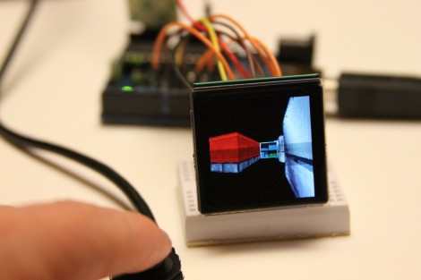
If you’ve ever thought of utilizing a small and inexpensive OLED display in your project [Rossum] has the details you need to get started. In the past we’ve seen him take a tour of available LCD screens and this is much the same, detailing his look at three different models. In the video after the break each is connected to a driver board that he made. The boards have two important components, the first is a boost driver for the 12-16V input the screens need, the second is an octal buffer necessary if you are using a 5V microcontroller. These take care of the hardware considerations, making it simple to drive them with a chip of your choosing.

Continue reading “OLED Displays And Small Microcontrollers”

1W Blue Laser – Remarkably Easy And Dangerous

[youtube=http://www.youtube.com/watch?v=lE3F7vjYx4U]

We’ve been covering Laser Hacks pretty much since the beginning but it’s surprising to see the niche market that has sprouted up around building powerful handheld modules. [Styropyro] filmed the video above as a tutorial on building a 1W blue laser. The “flashlight” that he starts with includes a heat sink intended for a laser diode. It seems there’s a lot of choices when choosing one of these build kits. A one Watt blue laser diode is press fit into the heat sink and wired in place. The body of the device receives a boost converter to get the batteries up to 1A, and once the assembly is complete the burning begins. It lights candles, matches, and pops balloons; the normal laser demo goodies.

So it’s a pretty easy build. But it’s also easy for someone being careless to damage their eyes. As [Styropyro] mentions in his comments, just looking at the dot created by the laser will damage your sight.

A More Powerful Boost Charger

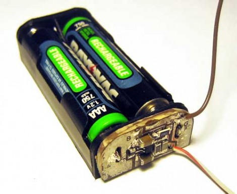
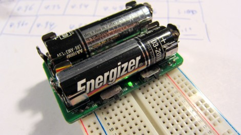
[Meseta] built a powerful boost charger to top off his portable devices. He was inspired by the Minty Boost but wanted to overcome the rather limited capacity provided by the two-celled product. He ended up building his own DC to DC boost circuit rather than using an all-in-one IC. As you can see, the result uses four 18650 lithium-ion cells, normally found in laptop batteries, and can power two USB devices at the same time.

Learn From The Ice Tube Clock

icetube

Looks like they’re at it again over at Adafruit. This time they’ve produced a clock that looks more like it should be attached to a munition rather than cruising bedside. But, geek-cred aside, there’s a lot to be learned from their design. Like we’ve grown to expect, they’ve put together some good documentation on their choice of components.

Start off by taking a peek at their 5v power regulator. There is an extra diode on the output side that prevents reverse current from the 3v backup battery. The AVR ATmega168 that controls the clock is used to detect loss of power and quickly shift to the battery backup. They’ve also used the  microcontroller as a boost converter for the high voltage VFD, a nice trick we’ve seen before.

[Thanks pt]

AVR Boost Converter

avrboost

Over at SpriteMods, [sprite_tm] realized that a microcontroller could be used as a boost converter to power itself. A boost converter steps up voltage from a battery by switching the output of a coil. First, it is tied to ground so a magnetic field can build up in the coil. It is then released as a higher voltage than the input. Normally dedicated chips do this at an incredibly high frequency, but the PWM signal from an AVR works well enough. This can be used in low-power situations where space is an issue.

[via EMSL]