DIY Surface Grinder For Making Precision Parts At Home

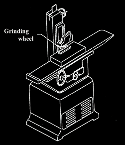
Surface Grinders are machines that can make a surface of a part very flat, very smooth and very parallel to the face of the part that is mounted to the machine. Surface grinders usually have a spinning grinding wheel suspended over a moving bed. The bed moves the part back and forth under the grinding wheel removing an extremely small amount of material at a time, sometimes down to just a ten-thousandth of an inch (o.0001″) in order to make a precision part.
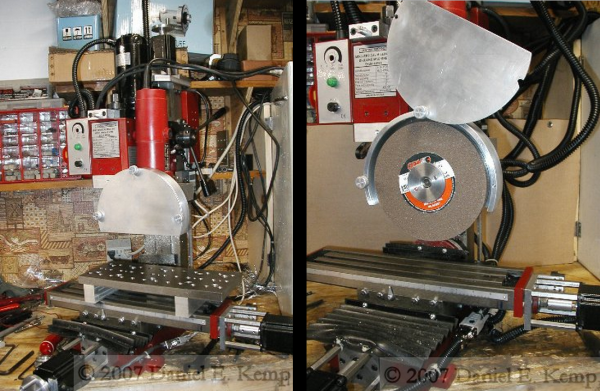
Surface Grinder DIY[Daniel] is a tool guy and wanted a Surface Grinder. He didn’t need a super-accurate commercial grinder so he decided to make one himself. It’s a doozy of a project and is made up of quite a few other tools. [Daniel] already had a mini CNC mill and decided this would be a good platform to begin with. The mill was rigid and already had automated X and Y axes, after all. For the grinder motor, nothing made more economical sense than to use a regular angle grinder, but there were two significant problems. First, no company made wide grinding wheels for an angle grinder. [Daniel] had to modify his spindle to accept an off-the-shelf surface grinding wheel. The second problem is that the new grinding wheel had a max RPM rating of 4400. The angle grinder can reach 10,600 RPM. In order to slow down the angle grinder, a speed control was taken out of an old variable-speed router and integrated with the angle grinder. Problem solved. A mount was then made to attached the angle grinder to the Z axis of the mill.

A magnetic chuck mounted to the mills bed is used to hold down metal work pieces. There is a lever on the chuck that when moved in one direction it creates a magnetic field to hold a ferrous piece of metal firmly to the chuck during machining. When the lever is moved in the other direction, the part is released and can be removed from the Surface Grinder.

To use his new Surface Grinder, [Daniel] creates a CNC g-code file to move his work piece back and forth underneath the grinding wheel. Being able to control the depth of cut and feed rates with his CNC machine removes human error from the grinding process and leaves a consistent finish on the part. Check out the video after the break.

Continue reading “DIY Surface Grinder For Making Precision Parts At Home”

CNC Milling Photos With A Halftone Generator

Looking for an awesome way to mill out a photo or graphic? Check out [Matt Venn]’s halftone gcode generator which creates halftone CNC toolpaths from any image file. We’ve run across some halftone generators before, but [Matt]’s generator has some interesting features and makes for some pretty unique output.

[Matt] initially wrote a simple command line program in Python, but just rewrote his script with a more user-friendly UI that renders a preview of the output as you change options.  The UI lets you change parameters like drill depth, number of lines, and the step size to tweak the output. It even has an option to map the halftone points along a sine wave which makes an interesting effect as shown in the image above.

[Matt]’s program generates standard gcode that you can use to run your CNC machine. [Matt] recommends milling a material with layers of different colors, but you can always mill a solid material and fill the routed areas with paint or dye instead. Want to grab the script or check out the source code? Head over to [Matt]’s GitHub repository.

Thanks for the tip, [Keith O].

Tumblemill

The Tumblemill: Homemade CNC Milling

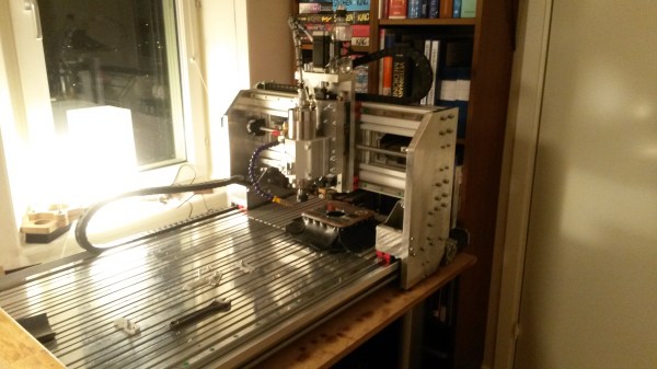
[Jens] aka [Tumblebeer] has compiled an impressive overview of the Tumblemill, his homemade CNC mill. It warms our hearts to learn that [Tumblebeer] was inspired to pursue electronics by projects featured here on Hackaday, even if it means he dropped out of med school to pursue electrical engineering. We’re glad he’s following his passion, though, and reading through his blog reveals just how far he’s come: from fiery disaster in his first projects to a gradual obsession with making a CNC device, [Tumblebeer] has made plenty of mistakes along the way, but that’s how it should be.

His first iteration was a CNC router that used rubber wheels as linear bearings. It worked…barely. His latest build grew out of meticulous Solidworks modelling, with a moving gantry design constructed largely from aluminum, and upgraded linear motion: this time a bit overkill, using HIWIN HGH20CA blocks. Rather than sourcing a traditional spindle mount, [Tumblebeer] opted for the housing from a LM50UU bearing, which provided both the perfect fit and a sturdier housing for his 2.2kw spindle.

Visit his project blog for the details behind the mill’s construction, including a lengthy installment of upgrades, and hang around for a demo video below, along with the obligatory (and always appreciated) inclusion of the Jolly Wrencher via defacing an Arduino.

Continue reading “The Tumblemill: Homemade CNC Milling”

Cryogenic Machining Custom Rubber Parts

Cryogenic Machining: Custom Rubber Parts

Fashioning a custom, one-off rubber part for your project isn’t usually an option, but [Ben Krasnow] has an alternative to injection molding and casting: machining frozen rubber.

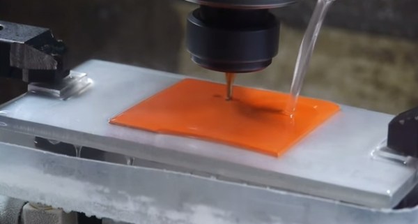
As [Ben] points out, you can’t exactly pop a sheet of rubber on your mill and CNC the needed shape; the bit will push the material around rather than cut it. Freezing the rubber first, however, allows you to carve into the now-hardened material.

His initial setup consisted of a sheet of aluminum with water drizzled on top, a square of neoprene placed on the water, and a steady stream of -60 to -80C alcohol flowing directly onto the rubber. The water underneath freezes, holding the neoprene in place. This proved problematic as the ice-clamp gives way before the milling is complete. [Ben] later adds some bolts to clamp the pieces down, allowing the milling process finish as planned.

A small plastic tray sits underneath this assembly to capture the alcohol as it runs off, feeding it back with some tubing. [Ben] recommends against a submersible aquarium pump—his initial choice—because the pump stopped working after a few minutes immersed in the chilly alcohol. An external, magnetically-driven pump solved the problem although it does require manual priming.

Stick around after the jump for the video and check out some of [Ben’s] other projects, like his quest for the perfect cookie, or CT scanning a turkey.

Continue reading “Cryogenic Machining: Custom Rubber Parts”

Brushless DC Motor Used For High Speed CNC Spindle

Brushless DC Motor CNC Spindle

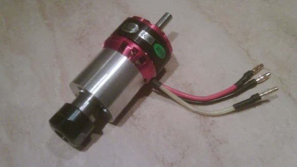
Brushless DC motors are common place in RC Vehicles. They are small, light, fast and can be inexpensive. [Raynerd] wanted a new spindle for his CNC machine and thought that a brushless DC motor would be a great platform to build from.

[Raynerd] started with an off the shelf motor that had an 8mm shaft. This shaft size was important because the motor shaft was to be replaced with an ER16 collet arbor of the same size. A collet is a device used to hold cutting tools by collapsing a segmented ring around the tool. Collets allows for quick tool changes while providing a strong clamping force. ER16 is a designation of one of many collet standards.

The main housing was machined out of aluminum specifically for this project. This housing holds two radial load ball bearings that support the new rotating collet arbor. There’s another bearing in this assembly, a thrust washer this time, that keeps the arbor from moving axially in the housing.

The 12 volt output of a standard ATX power supply was used to power the system for testing purposes. A general RC Vehicle electronic speed control and a servo tester work in conjunction to manually regulate the spindle speed. Check out the bench test video and an exploded photo after the break.

Continue reading “Brushless DC Motor Used For High Speed CNC Spindle”

Building A CNC Milling Machine For Less Than $1300

CNC milling machine

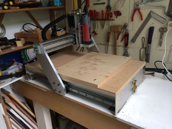
[Mynasru] tipped us about a homemade CNC milling machine that his friend [trochilidesign] recently made. We have to admit it may be one of the best ones we’ve featured so far on Hackaday, mainly due to its elegant design (see picture above) and its all metal structure with linear guide rails. In the very well detailed write-up, we can gather that the CNC machine was designed using SolidWorks.

The main frame is built around 2 Maytec 40x80mm profiles and 2 endplates made from 10mm thick aluminum. 3 Nema 23 stepper motors and their drivers power the build, all of them bought on ebay. Finally, the Mach3 CNC software was chosen to interpret the G code and send the appropriate control signals.

Due to licensing restrictions the original author can only provide us with PDF files detailing each part of the machine, but we’re sure this should already be enough for interested persons out there.

Three Axis Position Indicator With Digital Calipers

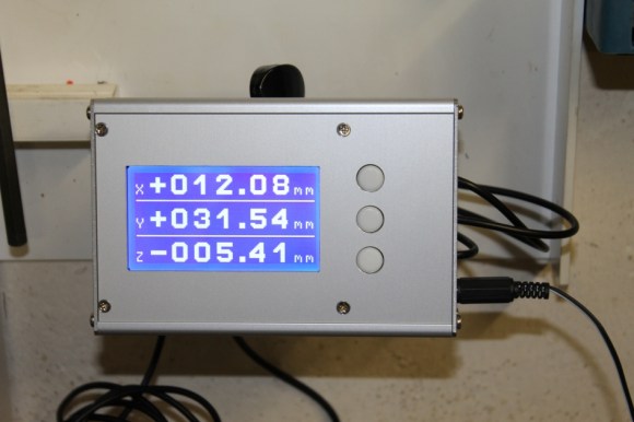
[Malte] just finished a little project for his Wabeco F1200 milling machine: a compact external display for three digital sliding calipers (Translated from German). As you may have already guessed, [Malte] was lucky enough to be able to fit disassembled calipers onto the machine and use them for positioning. Before embarking on this adventure, he noticed that there were similar projects present on the internet, but all of the calipers used had different data interfaces and protocols. The calipers that [Malte] bought have a mini USB connector, even though the interface itself isn’t USB. As he couldn’t find any information on that interface, he turned to his oscilloscope to decode the protocol.

[Malte] then built an AVR-based platform that reads out the three calipers and shows the position data on the dot matrix LCD shown above. The AVR firmware is written in a mixture of Basic and assembler language. The source code, schematics, and other resources can be downloaded from the project’s web page. We are impressed on the professional aspect of the final result.

Continue reading “Three Axis Position Indicator With Digital Calipers”