Secrets Of The Old Digital Design Titans

Designing combinatorial digital circuits seems like it should be easy. After all, you can do everything you want with just AND, OR, and NOT gates. Bonus points if you have an XOR gate, but you can build everything you need for combinatorial logic with just those three components. If all you want to do is design something to turn on the light when the ignition is on AND door 1 is open OR door 2 is open, you won’t have any problems. However, for more complex scenarios, how we do things has changed several times.

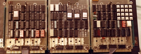
In the old days, you’d just design the tubes or transistor circuits you needed to develop your logic. If you were wiring up everything by hand anyway, you might as well. But then came modules like printed circuit boards. There was a certain economy to having cards that had, say, two NOR gates on a card. Then, you needed to convert all your logic to use NOR gates (or NAND gates, if that’s what you had).

Small-scale ICs changed that. It was easy to put a mix of gates on a card, although there was still some slight advantage to having cards full of the same kind of gate. Then came logic devices, which would eventually become FPGAs. They tend to have many of one kind of “cell” with plenty of logic gates on board, but not necessarily the ones you need. However, by that time, you could just tell a computer program what you wanted, and it would do the heavy lifting. That was a luxury early designers didn’t have. Continue reading “Secrets Of The Old Digital Design Titans”

Row of white 3D printed shoes in different styles

CAD Up Some Shoes, But Don’t Start From Scratch

Nothing helps a project get off the ground better than a good set of resources, and that’s what led [DaveMakesStuff] to release his Digital Shoe Design Kit, which is a set of 3D models ready to customize into a basic running shoe.

This is exactly what is needed for people who are interested in designing a custom shoe, but perhaps not interested in modeling every element entirely from scratch. [DaveMakesStuff]’s resources allows one to mix outsoles, midsoles, uppers, and other basic shoe elements into a finished model, ready to be resized or even 3D printed if desired. The files are all in stl format, but resizing stl files is trivial, and more advanced editing is possible with mesh sculpting programs like Blender.

If the gears in your head are starting to turn and you are wondering whether it is feasible to 3D scan your feet for some experiments in DIY custom footwear, take a few minutes and read up on 3D scanning and what to expect from the process to hit the ground running.

Survey Of Simple Logic Simulators

A few months ago, a tweet by [Ken Shirriff] asking about simple digital simulators caught my attention. The topic came up again in May when a repair video by [CuriousMarc] featured one such simulator called Logisim-evolution. It made me want to take a fresh look on what’s out there and which features set the different simulators apart.

So today, let’s take a quick survey of a few such simulators that I found. I’m focusing on plain logic simulators, analyzing ones and zeros using Boolean logic. They are not doing SPICE-like analog analysis of transistor logic gates, but they’re still quite handy for proofing out designs.

Continue reading “Survey Of Simple Logic Simulators”

Digital Designer Teaches High School

We wish we had met [Mr. Mueller] when we were in high school. After 20 years as a digital design engineer, he decided to teach a digital electronics class at the high school level at LASA high school in Austin, Texas. He’s been doing it for seven years and has made his course material available via Google Docs.

Don’t let the high school level fool you. Topics range from simple electronics to Spice. There’s coverage of discrete devices, oscilloscopes, and Arduinos. There’s plenty of digital logic, of course, and a simple 16-bit microprocessor, too. There are labs for FPGAs using Verilog and talks about ARM. It’s pretty comprehensive and we wonder if they can really cram all this into a single school year. One thing we saw that caught our eye was the simulation of a transistor using Play-Doh. Turns out it isn’t an electrical simulation, but a simulation of how photolithography creates transistors. Still good stuff.

This would be great for teaching students of pretty much any age, even if you took only parts of it. It would also be worthwhile for self-study. We know how much work it takes to put something like this together, and we can’t commend [Mr. Mueller] and the LASA high school enough for making it available to everyone.

There is more and more course material out there at all levels and we think that’s a great thing. If you need something for a younger set, try a blindfold.

Becoming A State Machine Design Mastermind

Imagine a robot with an all-around bump sensor. The response to the bump sensor activating depends on the previous state of the robot. If it had been going forward, a bump will send it backwards and vice versa. This robot exhibits behavior that is easy to model as a state machine. That is, the outputs of the machine (motor drive) depend not only on the inputs (the bump sensor) but also on the current state of the machine (going forward or backward).

As state machines go, that’s not an especially complicated one. Many state machines have lots of states with complex conditions. For example, consider a phone switchboard. The reaction to a phone going off hook depends on the state of the line. If the state is ringing, picking up the phone makes a connection. If the state is idle, the phone gets a dial tone. The switchboard also has to have states for timeouts, connection failures, three way calling, and more.

If you master state machines your design and debug cycles will both move along faster. Part of this is understanding and part is knowing about the tools you can choose to use. I’ll cover both below.

Continue reading “Becoming A State Machine Design Mastermind”

The Trials Of Digital Design Class

Late last week, we saw a rather clever combination lock build that used only a single 74xx logic chip. [J. Peterson] read this post, and in a battle royale of geek one upmanship sent us a write up of the logic chip computer he built nearly 30 years ago at the University of Utah.

Around 1982 or 1983, [J. Peterson] took the Digital Hardware Lab at the University of Utah. The class was split into two semesters; during the fall semester, students would build a four digit, stack-based calculator that could add and subtract. That may sound easy, but everything – including reading the keyboard, multiplexing LEDs, and performing the mathematical operations – was done with gates and latches.

After Christmas break, the poor souls who had just finished their calculator were presented with another challenge due in four short months. The calculator built during the fall would turn into a full-blown computer, functionally similar to a PDP-8.

After months of work, and seeing the 70 people who showed up on the first day of class in September dwindle down to a handful in late April, [J. Peterson]’s computer was complete. The test program ran through a couple iterations, and the computer was immediately disassembled.

An awesome tale of digital design from only a generation ago. And you thought Verilog was hard.