Most Of What You Wish You Knew About Coils Of Wire But Were Afraid To Ask

If you are a novice electronic constructor, you will become familiar with common electronic components. Resistors, capacitors, transistors, diodes, LEDs, integrated circuits. These are the fodder for countless learning projects, and will light up the breadboards of many a Raspberry Pi or Arduino owner.

There is a glaring omission in that list, the inductor. True, it’s not a component with much application in simple analogue or logic circuits, and it’s also a bit more expensive than other passive components. But this omission creates a knowledge gap with respect to inductors, a tendency for their use to be thought of as something of a black art, and a trepidation surrounding their use in kits and projects.

We think this is a shame, so here follows an introduction to inductors for the inductor novice, an attempt to demystify them and encourage you to look at them afresh if you have always steered clear of them.

Continue reading “Most Of What You Wish You Knew About Coils Of Wire But Were Afraid To Ask”

Building A Transistor Clock From Scrap

[Phil] has already built a few clocks with Nixies, VFDs, and LED matrices. When his son requested his own clock, he wanted to do something a little different. Inspired by the dead bug style of [Jim Williams]’ creations, [Phil] set out to build a clock made entirely out of discrete components. That includes the counters, driver circuits, and an array of LED.

There are a few inspiration pieces for [Phil]’s clock, starting with the Transistor Clock, a mains-powered clock that uses 194 transistors, 566 diodes, and exactly zero integrated circuits. Design patterns from a clock so beautiful it’s simply called The Clock are also seen, as is a Dekatron emulator from [VK2ZAY].

[Phil]’s creation has no PCB, and all the components are soldered onto tiny wires arranged into something resembling the clocks circuit. It’s a fantastic contraption, and while we’ll still have to give the design award to the clock, [Phil]’s creation shows off the functional circuits; great if he’ll ever need to debug anything.

Electronic Puzzle Box Uses Only Discrete Components

Puzzle box

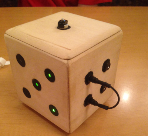
Do you need an idea for a fun do it yourself gift for a friend or significant other? Look no further, [conductance] has you covered. He put together an awesome electronic puzzle box using all analog electronics. The puzzle case is shaped like an over sized die and is made out of wood. It also requires a small jumper cable and an external magnet to complete the puzzle.

This is a six-sided die, where each side has something different to offer. The “five” side of the die shows the progress you’ve made in completing the puzzle. Each of the five dots contains a green LED that will light up when the corresponding puzzle has been successfully completed.

The “one” side is completed by placing the included magnet over the dot. The magnet activates a reed switch which lights up the first LED. The “two” side contains a tilt switch. In order to solve this piece of the puzzle you must ensure the two side is facing up, as if you rolled a two. The “three” side contains three key switches. Each switch must be turned to a particular orientation. Once all three keys are configured properly, a third LED lights up.

The “four” side contains four sockets that fit the included jumper cable. This puzzle is solved by jumping the two correct sockets together. Finally, the number “six” side just has six momentary push buttons. All six buttons must be pressed simultaneously in order to light up the final LED. The tricky part is pressing all six buttons while simultaneously “rolling” a two in order to ensure the tilt switch is also activated.

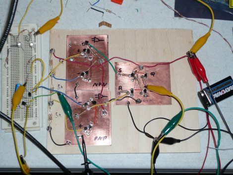
Once all five LED’s are lit up, a relay is triggered which then activates a solenoid. The solenoid unlocks the door and reveals the prize. It’s always great to see electronics circuits like this that use all discrete components. This could have been accomplished any number of ways, but there’s something satisfying about a simple circuit that’s just right for the job. Be sure to check out [conductance’s] schematic if you want to see how this puzzle works.

[via Reddit]

Building A 555 Timer From Discrete Components

The 555 Design Contest shook a whole bunch of really creative circuits out of the trees, hence the 555-heavy content lately. While not technically part of the contest, [esalazar] wanted to know what made the 555 tick, literally! He started working on the project in a circuit simulator, then ultimately ended up building the three main logic blocks inside the familiar timer on pieces of copper-clad board. He’d built a 555 using discrete components.

While this isn’t 100% compatible with the classic 555 IC, it covers the basics pretty well, and [esalazar] gets extra-credit points for embracing the hacker spirit of seeing for himself how stuff works while documenting it well and citing his references.