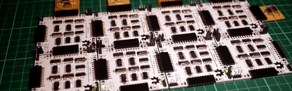
Regular Hackaday readers will be familiar with all the cool things you can do with FPGAs; emulating old video game consoles, cracking encryption protocols, and DIY logic analyzers become relatively simple projects with even a modest FPGA dev board on your workbench. Many FPGA boards aren’t geared towards prototyping, though, and breadboard friendly devices are hard to come by. Here’s a pair of breadboardable FPGAs we’ve found while searching for some related hardware over the past few days
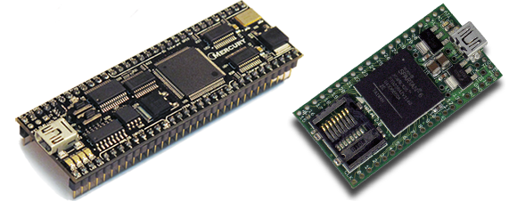
First up is the Mercury FPGA Module. Packaged in a DIP-64 format, the Mercury features a Spartan-3A FPGA with the equivalent of 200k logic gates. Elsewhere on the board is 512kB of RAM and 128kB of Flash storage. There are enough GPIO pins for nearly any project, but sadly only a 10-bit ADC – the same resolution you’d find in an AVR or PIC ‘micro.
Of course the Mercury isn’t the only breadboard-friendly FPGA dev board out there. There’s also the slightly more capable XuLA2 board powered by a Spartan-6 with 32 MB of RAM, 1MB of Flash. Unlike the Mercury, the XuLA2 can also fit in one of those ‘half-sized’ solderless breadboards.
Yes, it’s a different form factor than the commonly recommended Papilio One or the DE0. If you can suggest any other ‘beginners’ (i.e. doesn’t cost an arm and a leg) FPGA boards, leave a note in the comments and we’ll summarize them in another post.