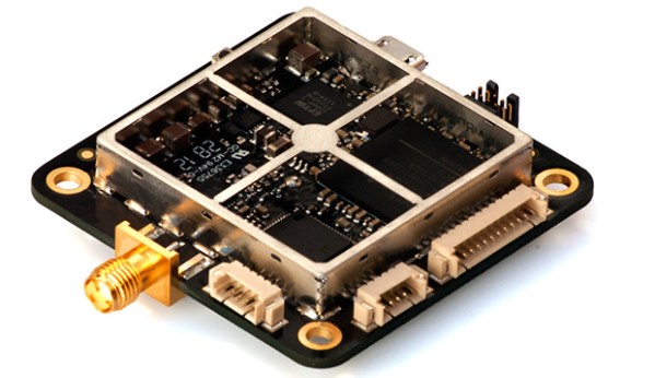
Centimeter-level Precision GPS For $900

[Colin] and [Fergus] have been working with GPS for years now, and like most builders of really cool things, they’re often limited by the precision of off-the-shelf GPS units. While a GPS receiver is usually good for meters of accuracy,  this just isn’t good enough for a lot of projects. What you need is centimeter-level accuracy, something the guys have managed to do with their Piksi GPS receiver.

Where most GPS receivers only look at the data coming from the GPS satellites orbiting overhead, the Piksi uses another technique, real-time kinematics (RTK), to determine the receiver’s location with exacting precision. The basic idea behind RTK is to look at the carrier frequency of the GPS signals at 1575.42 MHz. This frequency has a wavelength of 19 cm, compared to the alternating 1s and 0s of the that are transmitted at around 1 MHz, or about 300 meters between each bit. While centimeter-level precision isn’t possible with only one receiver, two of these Piksi boards – one base station and one on a vehicle, connected via radio link – can make for a very exacting high-accuracy GPS receiver.

Previously, commercial RTK GPS systems have cost thousands of dollars – making a quadcopter or other homebrew project that relies on this level of precision nonsensical. [Colin] and [Fergus] have built hardware that can bring the price of this setup to under $1000. As a bonus, the Piksi board can also receive from other constellations such as Galileo and GLONASS. A very impressive piece of hardware, and we can’t wait to see the applications.

Rocketduino, For High-G, High Altitude Logging

rocketduino

Although the thrill of launching rockets is usually found in their safe decent back to Earth, eventually you’re going to want some data from your flight. Everything from barometric pressure, GPS logging, and acceleration data is a useful thing to have, especially if you’re trying to perfect your craft. [zortness] over on reddit created a data logging board created especially for amateur rocketry, a fabulous piece of work that stands up to the rigors of going very fast and very high.

The design of the board is a shield for the Arduino Mega and Due, and comes with enough sensors for over-analyzing any rocket flight. The GPS logs location and altitude at 66Hz, two accelerometers measure up to 55 G. Barometric, temperature, and compass sensors tell the ground station all the data they would need to know over a ZigBee 900MHz radio link.

Because this is an Arduino, setting up flight events such as deploying the main and drogue chutes are as easy as uploading a bit of code. [zortness] built this for a 4″ diameter rocket, but he says it might fit in a 3″ rocket. We just can’t wait to see some videos of it in action.

Wireless Rover With Android Control

android-rover

[Radu] spend the first portion of this year building and improving upon this wireless rover project. It’s actually the second generation of an autonomous follower project he started a few years back. If you browse through his old postings you’ll find that this version is leaps and bounds ahead of the last.

He purchased the chassis which also came with the gear-head motors and tires. Why reinvent the wheel (har har) when you’ve got bigger things on your plate? To make enough room inside for his own goodies he started out by ditching the control board which came with the Lynxmotion chassis in favor of an AVR ATmega128 development board. He also chose to use his own motor controller board. Next he added a metal bracket system to hold the battery pack. Things start to get pretty crowded in there when he installed his own Bluetooth and GPS modules. Rounding out his hardware additions were a set of five ultrasonic sensors (the grey tubes on top), a character display, as well as head and tail lights. The demo video shows off the control app he uses. We like that tic-tac-toe design for motion control, and that he added in buttons to control the lights.

Continue reading “Wireless Rover With Android Control”

Homebrew GPS Gets ±1 Meter Resolution With A Raspberry Pi

GPS

We’ve been following the work of [Andrew Holme] and his homebrew GPS receiver for a while now. A few years ago, [Andrew] built a four-channel GPS receiver from scratch, but apparently that wasn’t enough for him. He expanded his build last year to track up to eight satellites, and this month added a Raspberry Pi for a 12-channel, battery-powered homebrew GPS receiver that has an accuracy of about 3 feet.

The Raspi is attached to an FPGA board that handles the local oscillator, real-time events, and tracks satellites automatically. The Pi handles the difficult but not time-critical math through an SPI interface. Because the Pi is attached to the FPGA through an SPI interface, it can also load up the FPGA with even more custom code, potentially turning this 12-channel receiver into a 16- or 18-channel one.

An LCD display attached to the FPGA board shows the current latitude, longitude, and other miscellaneous data like the number of satellites received. With a large Li-ion battery, the entire system can be powered for about 5 hours; an impressively portable GPS system that rivals the best commercial options out there.

This GPS Logger Is So Small…

small-gps-logger

How small is it? Two things should give you a good sense of scale, the SD card slot on the lower right, and the slide switch on the upper left. This minuscule module is an all-in-one GPS logger which [J3tstream] built.

Main system control is provided by a Teens 2.0 board. If you look really closely you’ll see the SD card slot is actually a breakout board which mounts on top of the Teensy’s pinheaders. Also on the board is a PA6B GPS module with a few passive components to support it. The back side of the board hosts a Lithium Ion battery from an old phone. Note the mangled pin header which works as connectors for the battery. [J3tstream] even built a charger into the project. He’s using an LTC4054 chip to handle the charging. We were a bit confused at first because we didn’t see a way to connect external power. But he goes on to explain that the USB port on the Teensy board is used for charging. Just plug in USB and press the button to get things started.

Snowboard Goggle HUD Displays Critical Data While Falling Down A Mountain

snowboard-google-hud

[Chris] has been hard at work building a Heads Up Display into some Snowboarding goggles. We’re used to seeing the components that went into the project, but the application is unexpected. His own warning that the display is too close to your face and could cause injury if you were to fall highlights the impractical nature of the build. But hey, you’ve got to start somewhere when it comes to prototyping. Perhaps the next iteration will be something safe to use.

A set of MyVu glasses were added to the top portion of the goggles, which lets the wearer view the LCD output by looking slightly up. The display is fed by a Raspberry Pi board which connects to a GPS module, all of which is powered by a USB backup battery. In the video after the break you can see that the display shows time of day, speed, altitude, and temperature (although he hasn’t got a temperature sensor hooked up just yet). His bill of materials puts the project cost at about £160 which is just less that $250.

Continue reading “Snowboard Goggle HUD Displays Critical Data While Falling Down A Mountain”

Putting The Brains Of A Reverse Geocache On The Outside

ioio

A reverse geocache – a box that only opens in a specific geographical area – is a perennial favorite here at Hackaday. We see a ton of different implementations, but most of the time, the builds are reasonably similar. Of course dedicating a GPS receiver solely to a reverse geocache isn’t an inexpensive prospect, so [Eric] came up with a better solution. He’s using a smart phone as the brains of his geocache, allowing him to keep the GPS and display outside the locked box.

The build began by finding an old box and modifying it so it can be locked with a servo. The only other bits of electronics inside the box are an IOIO board, a battery pack, and an I2C EEPROM for storing a few settings. On the phone side of things, [Eric] wrote an Android app to serve as both the programming interface, UI, and GPS hardware for his reverse geocache. It’s exactly like all the other reverse geocaches we’ve seen, only this time the controls are wireless.

[Eric] put up a video demoing his reverse geocache. You can check that out after the break.

Continue reading “Putting The Brains Of A Reverse Geocache On The Outside”