Quadcopter Brain

quadcopter-brain

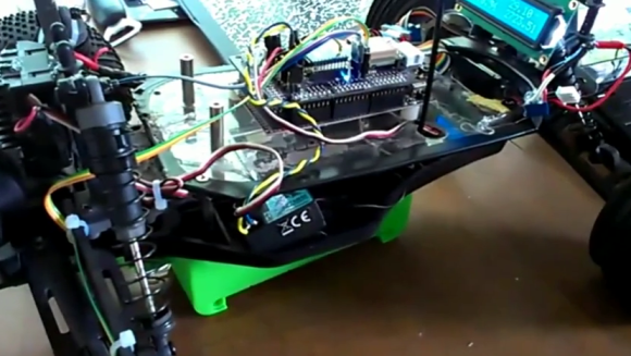
This project is the warm center of [Alan Kharsansky’s] thesis in Electronic Engineering. It’s an all-in-one control board for a quadcopter. This is the second iteration of the board, the first version he actually etched himself. As you can see after the break the firmware is not quite ready for prime-time. But that doesn’t stop us from appreciating the design choices he’s made.

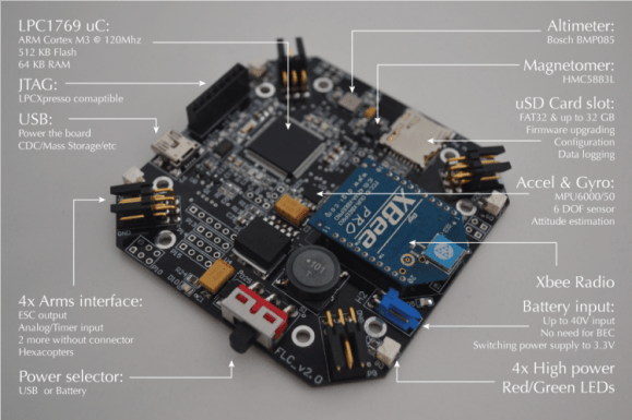
You can see the effort he made to keep the board symmetrical which will help when it comes time to balance the aircraft. At the center of the PCB is the jewel of the sensor array, a combination accelerometer and gyroscope. This location will help easy the trouble of designing PID algorithms to drive the four propellers. Also included in the sensor array is a magnetometer for navigation, and a barometric pressure sensor which can be used as an altimeter. There are four multipurpose connectors used to drive the motors and provide feedback to the boards. He also included two more sets of pads on the board (without their own connectors) in case he wants to add more motors in the future. The quadcopter can be controlled from a base station via the XBee module.

Continue reading “Quadcopter Brain”

Tutorial Explains The Concepts Behind An IMU

[Anilm3] wrote in to share the IMU tutorial series he is working on. An Inertial Measurement Unit is most often found in self-balancing robots and quadcopters, providing enough high-speed sensor data to keep up with the effects of gravity.  He previously used some all-in-one IMU devices in school which did most of the work for him. But he wanted to grind down and look at what each sensor spits out and how those measurements are used. The first installment deals with the accelerometer, using its data to calculate pitch and roll. For these demonstrations [Anilm3] is using this ADXL345 sensor board, an Arduino, and some processing sketches for testing.

Whenever working with sensors you need to take noise into consideration. The post shows how to implement a low-pass filter in the code which will help smooth out the readings. The filtered data is then fed to a couple of mostly-painless formulas which calculate the movement of the accelerometer in degrees. The demonstration sketch is mapped to a 3D cube to give you an idea of how accurate the accelerometer is. There’s a little bit of lag which would let a self-balancing robot have a nasty fall. The solution to this issue will be discussed in upcoming parts of the series. The next installment tackles the gyroscope sensor.

Kalman Filter Keeps Your Bot Balanced

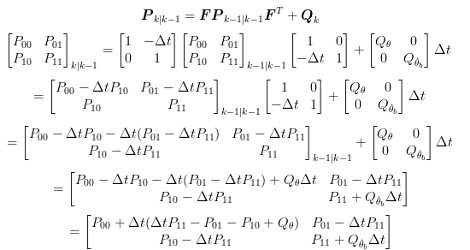
If you’re looking to improve the stability of your self balancing robot you might use a simple horrifying equation like this one. It’s part of the journey [Lauszus] took when developing a sensor filtering algorithm for his balancing robot. He’s not breaking ground on new mathematical ideas, but trying to make it a bit easier for the next guy to use a Kalman filter. It’s one method of suppressing noise and averaging data from the sensors commonly used in robotic applications.

His robot uses a gyroscope and accelerometer to keep itself upright on just two wheels. The combination of these sensors presents an interesting problem in that accelerometer input is most accurate when sampled over longer periods, and a gyroscope is the opposite. This filter takes those quirks into account, while also factoring out sensor noise. Despite the daunting diagram above, [Lauszus] did a pretty go job of breaking down the larger function and showing us where to get the data and how to use it in microcontroller code.

Self Balancing Robot Uses Cascading PID Algorithms

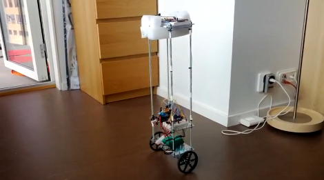
At this point we’re beginning to think that building a self-balancing robot is one of the rights of passage alongside blinking some LEDs and writing Hello World on an LCD screen. We’re not saying it’s easy to pull off a build like this one. But the project makes you learn a lot about a wide range of topics, and really pushes your skills to the next level. This latest offering comes from [Sebastian Nilsson]. He used three different microcontrollers to get the two-wheeler to stand on its own.

He used our favorite quick-fabrication materials of threaded rod and acrylic. The body is much taller than what we’re used to seeing and to help guard against the inevitable fall he used some foam packing material to protect the top level. Three different Arduino boards are working together. One monitors the speed and direction of each wheel. Another monitors the IMU board for position and motion feedback, and the final board combines data from the others and takes care of the balancing. Two PID algorithms provide predictive correction, first by analyzing the wheel motion, then feeding that data into the second which uses the IMU feedback. It balances very well, and can even be jostled without falling. See for yourself in the clip after the break.

Continue reading “Self Balancing Robot Uses Cascading PID Algorithms”

Cracking Open An Ancient Avionics Gyroscope

This artificial horizon might as well have come from an alien ship. [Mike] somehow manages to get his hands on most interesting equipment, this time its a very old piece of avionics equipment. The mechanical gyroscope functioned as the artificial horizon, and he’s going to take us inside for a look. He doesn’t spend quite as much time on it as he did that thermal imaging camera, but this electro-mechanical odyssey is just as interesting.

To get the accuracy needed to help keep a plane in the air (well to keep the pilot well-informed anyway) the device needed to be very well manufactured. [Mike] comments several times along the way on how the different rotating parts are so well-balanced and machined that they seem nearly frictionless. It appears that a lot of the positional feedback depends on wirewound resistor rings which connect to a rotating piece via a series of very fine spring wires. As the parts rotate the resistance changes and that’s what gives the feedback. There are also mercury switches to help along the way.

He does his best to explain, but to us the inner workings are still a big mystery. See if you can get a clearer picture from the video after the break.

Continue reading “Cracking Open An Ancient Avionics Gyroscope”

Printing And Programming A Self-balancer

The Hackaday staff isn’t in agreement on 3d printers. Some of us are very enthusiastic, some are indifferent, and some wonder what if they’re as widely useful as the hype makes them sound. But we think [Jason Dorweiler’s] self balancing robot is as strong a case as any that 3d printing should be for everyone!

Don’t get us wrong. We love the robot project just for being a cool self-balancer. Seeing the thing stand on its own (video after the break) using an Arduino with accelerometer and gyroscope sensors is pure win. But whenever we see these we always think of all the mechanical fabrication that goes into it. But look at the thing. It’s just printed parts and some wooden dowels! How easy is that?

Sure, sure, you’ve got to have access to the printer, it needs to be well calibrated, and then you’ve got to make the designs to be printed out. But these hurdles are getting easier to overcome every day. After all, there’s no shortage of people to befriend who want nothing more than to show off their Makerbot/RepRap/etc.

Continue reading “Printing And Programming A Self-balancer”

Gyroscopically Stabilized Car/motorcycle Thing

So yeah, this thing exists. Well, at least some pretty interesting looking prototypes of it do. It’s the C-1 from Lit Motors (anyone else think that’s a reference which belongs in /r/trees?). The idea here is that the small form-factor of a motorcycle is very efficient and easily maneuverable. But the cage protecting the passenger from harm, and the canopy keeping the elements out give it some of the desirable traits of a car.

Design aside, check out the video after the break. The prototype uses two horizontally positioned gyroscopes placed beneath the passenger seat, just in front of the rear wheel. The builders take it out on a hockey rink and give it a few kicks and slide a few tires into it. Sure, it reacts to the impact but it doesn’t fall over.

Want to see some fast-motion welding of the C-1? Right now there’s a one-minute clip up on the company’s main page.

Continue reading “Gyroscopically Stabilized Car/motorcycle Thing”