Homebrew Dash Cam Enables Full Suite Of Sensors

You heard it here first: dash cams are going to be the next must-have item for your daily driver. Already reaching market saturation in some parts of the world but still fairly uncommon in North America, we predict that car makers will soon latch onto the trend and start equipping cars with dash cams as standard equipment. And you can just bet that whatever watered-down, overpriced feature set they come up with will be sure to disappoint, so you might want to think about building your own Raspberry Pi dash cam with an accelerometer and lots of LEDS.

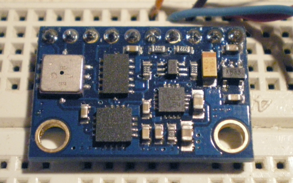
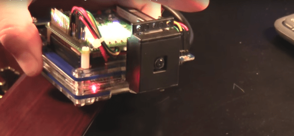
Still very much in the prototyping phase, [CFLanger]’s project is at its heart a dash cam, but it looks like he wants to go far beyond that. Raspivid and a PI NoIR camera take care of the video streaming, but the addition of a Pi SenseHAT gives [CFLanger] a bunch of options for sensing and recording the car’s environment. Not content with the SenseHAT’s onboard accelerometer, he added an ADXL345 to the sensor suite. The 64-pixel LED display is just for fun – it displays pitch and roll of the platform – and a yet-to-be-implemented bar-graph display will show acceleration in the X-axis. He figures the whole thing is good for a couple of days of video, but we hope he adds audio capture and perhaps ECU data from an OBDII-Bluetooth adapter.

We’ve seen surprisingly few DIY dash cams on Hackaday, at least so far. There has been a dash cam teardown and retasking, and there are plenty of dashboard computer builds, though. Seems like most hackers want that DIY self-driving car first.

Continue reading “Homebrew Dash Cam Enables Full Suite Of Sensors”

IoT Enabled Thomas The Tank Engine

This month the popular “Thomas the Tank Engine” toy celebrated its 70 anniversary. As a fun project, [tinkermax] wanted to bring this traditional toy into the age of IoT, while preserving its physical appearance and simple charm.

He used a model called the “Diesel” which seemed big enough to house the electronics, but proved otherwise once he inspected the innards. He needed to fit in an ESP8266 module, an accelerometer breakout, some discrete parts, a nifty analog multiplexer, and a 14500 3.7V LiPo. Once done, he was able to control its speed remotely over WiFi, with an auto “throttle-boost” that kicks in when the accelerometer senses that the train is going uphill, and has remote monitoring of battery state, engine load, inclination and track vibration – all in real-time using MQTT over WiFi. It’s quite a demonstration of the power of these super-cheap WiFi modules that are powering the current wave of IoT innovation.

The train motor works off a single 1.5V battery, so [tinkermax] tried a couple of boost converters to get the ESP-12 to work. But the modules were a tad bigger, and couldn’t provide the high peak current needed by the ESP-12. So he used a 14500 3.7V LiPo battery instead. A series diode drops the LiPo voltage to a circuit friendly 2.9V ~ 3.6V range. The ADXL345 accelerometer is used to measure “pitch” to detect going up and down a hill, “roll” to check for tilt or tip over and vibration to identify track defects. It communicates with the ESP-12 using a special Lite-SPI library that he wrote.

Two analog measurements are performed. One uses a resistor in series with the PWM driven motor to measure its current, with a low pass filter to smooth out PWM noise. The other is a resistor divider network used to monitor battery voltage. But the ESP-12 has just one ADC channel. Instead of adding another ADC module, [tinkermax] used a neat device – the FSA3157 – which allows two analog inputs to be channeled to a single output much like a SPDT switch. One PWM output is used to control motor speed and a second one to pulse a LED.

The sensor data is streamed 5 times a second over the MQTT protocol to a Raspberry Pi based MQTT broker. Finally, a JavaScript webpage receives the MQTT messages and plots the data graphically. One upgrade he would like to implement is speed measurement, to allow constant speed drive. If you have any ideas on how to extract that information from an accelerometer, chip in with your comments below. Check out his build log in the short video below. And if you’d like to see how all of this can be used in the real world, check this other video where [tinkermax]’s colleague gives a run down about a commercial enterprise IoT cloud platform hooked up to Thomas the Tank Engine.

Continue reading “IoT Enabled Thomas The Tank Engine”

TRINKET EDC CONTEST ENTRY: Lazydoro

[Vasilis] has entered Lazydoro in the Trinket Everyday Carry Contest.  Lazydoro is designed to get him up off his backside, and walking around. Recent medical research has determined that sitting too long is a bad thing. In fact,  Dr. David Agus has been quoted by Nike as saying that sitting for several hours is as bad as smoking (wayback machine link). While we’re not exactly up on the latest medical trends, we can definitely see that getting up and walking around a bit never hurt anyone. Lazydoro will alert [Vasilis] once every 20 minutes or so to get up and stretch his legs a bit.

[Vasilis] plans to pair a Pro Trinket with an accelerometer module, specifically an ADXL377 from Analog Devices. The accelerometer will allow Lazydoro to determine if [Vasilis] has moved around. If 20 or 30 minutes go by without major movement, Lazydoro will nudge him to get up and take a walk.

Since shipping to Greece takes awhile, [Vasilis] is developing with an Arduino Uno and a ADXL345 while he waits for his parts to arrive. He’s hacked this into a wrist mounted device for testing. One thing  [Vasilis]  hasn’t figured out yet is how to alert the user to move around. A small vibrating motor would probably work – but we’d suggest electric shocks. A good zap always puts the spring in our step!

There is still plenty of time to enter the Trinket Everyday Carry Contest.  The main contest runs until January 2, but we’re having random drawings every week! Don’t forget to write a project log before the next drawing at 9pm EDT on Tuesday, December 23. You and all of the other entrants have a chance to win a Cordwood Puzzle from The Hackaday Store!

Tutorial Explains The Concepts Behind An IMU

[Anilm3] wrote in to share the IMU tutorial series he is working on. An Inertial Measurement Unit is most often found in self-balancing robots and quadcopters, providing enough high-speed sensor data to keep up with the effects of gravity.  He previously used some all-in-one IMU devices in school which did most of the work for him. But he wanted to grind down and look at what each sensor spits out and how those measurements are used. The first installment deals with the accelerometer, using its data to calculate pitch and roll. For these demonstrations [Anilm3] is using this ADXL345 sensor board, an Arduino, and some processing sketches for testing.

Whenever working with sensors you need to take noise into consideration. The post shows how to implement a low-pass filter in the code which will help smooth out the readings. The filtered data is then fed to a couple of mostly-painless formulas which calculate the movement of the accelerometer in degrees. The demonstration sketch is mapped to a 3D cube to give you an idea of how accurate the accelerometer is. There’s a little bit of lag which would let a self-balancing robot have a nasty fall. The solution to this issue will be discussed in upcoming parts of the series. The next installment tackles the gyroscope sensor.

All About Accelerometers

If you’ve ever wondered about the use of or theory behind or the use of accelerometers, this tutorial by Love Electronics is a very good resource. In this article, Love takes one through how to hook up an ADXL345 accelerometer and use it with a Netduino processor. Before the subject of hooking everything up is broached, a very good discussion is given on the general theory and operation of accelerometers.

Information is given about installing all the required software and libraries. Additionally, a mini tutorial about writing a “hello” application using the .NET framework is given. Finally, the application gives the [Windows Presentation Foundation] tools necessary to visualize the raw data that the Netduino produces.

One could really start using this processor and accelerometer from scratch with this tutorial and some basic electronics knowledge.  This could add a great new feature to your next robot or allow measurement that couldn’t be done with simpler sensors.