In a clever bit of miniaturization, [JediJeremy] has nearly completed a gyro-mouse controller for a Raspberry Pi Zero! Ultimately this will be a wearable Linux-watch but along the way he had some fun with the interface.
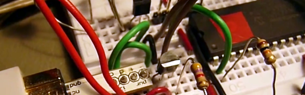
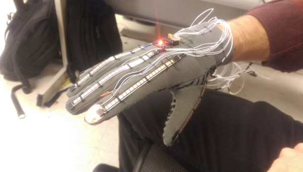
Using the MPU6040 gyroscope/accelerometer card from a quadcopter, [JediJeremy] spent a week writing the driver to allow it to function as a mouse. Strapping an Adafruit 1.5″ PAL/NTSC LCD screen and its driver board to the Zero with rubber bands makes this one of the smallest functional computer and screen combos we’ve seen. Simply tilt the whole thing about to direct the cursor.
It presently lacks any keyboard input, and [JediJeremy] has only added a single button for clicking, but look at this thing! It’s so tiny! In his own words: “I think this is the first computer that I can accidentally spill into my coffee, rather than vice versa.”
Continue reading “Raspberry Pi Zero Becomes Mighty Miniature Minecraft Machine”