Cool Tools: Deus Ex Autorouter

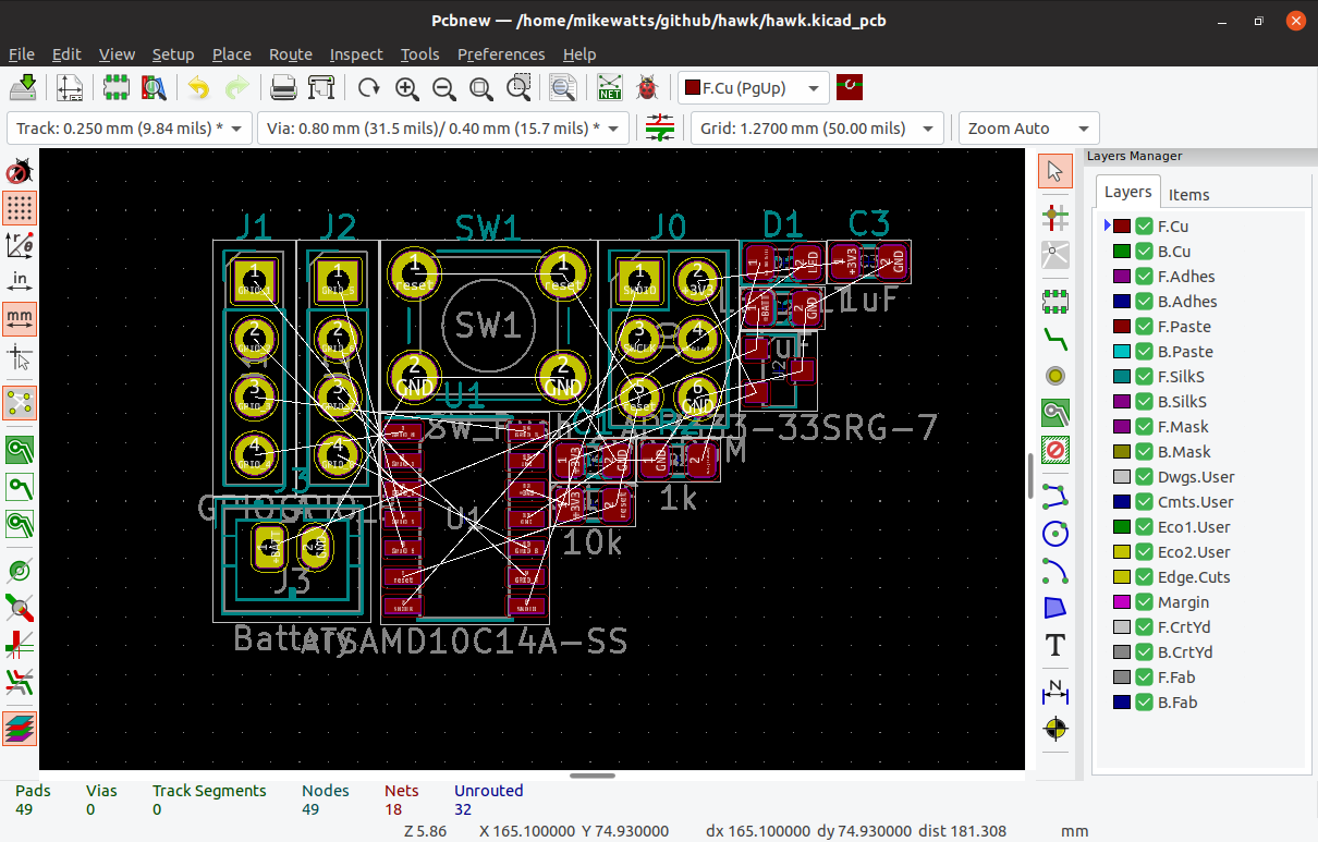
The first thing you probably asked yourself when learning how to lay out PCBs was “can’t the computer do this?” which inevitably led to the phrase “never trust the autorouter!”. Even if it hooks up a few traces the result will probably be strange to human eyes; not a design you’d want to use.

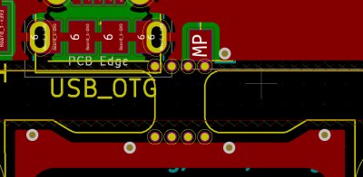
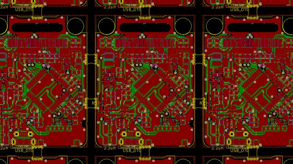
But what if the autorouter was better? What if it was so far removed from the autorouter you know that it was something else? That’s the technology that JITX provides. JITX is a company that has developed new tools that can translate a coarse textual specification of a board to KiCAD outputs autonomously.

Continue reading “Cool Tools: Deus Ex Autorouter”

Creating KiCad Parts From A PDF Automagically

For anyone out there who has ever struggled finding a part for Eagle or KiCad, there are some who would say you’re doing it wrong. You’re supposed to make your own parts if you can’t find them in the libraries you already have. This is really the only way; PCB design tools are tools, and so the story goes you’ll never be a master unless you can make your own parts.

That said, making schematic parts and footprints is a pain, and if there’s a tool to automate the process, we’d be happy to use it. That’s exactly what uConfig does. It automatically extracts pinout information from a PDF datasheet and turns it into a schematic symbol.

uConfig is an old project from [sebastien caux] that’s been resurrected and turned into an Open Source tool. It works by extracting blocks of text from a PDF, sorts out pin numbers and pin labels, and associates those by the relevant name to make pins. It’s available as a pre-built project (for Windows, even!), and works kind of like magic.

The video demo below shows uConfig importing a PDF datasheet — in this case a PIC32 — automatically extracting the packages from the datasheet, and turning that into a schematic symbol. It even looks as if it’ll work, too. Of course, this is just the schematic symbol, not the full part including a footprint, but when it comes to footprints we’re probably dealing with standard packages anyway. If you’re looking to build a software tool that takes a datasheet and spits out a complete part, footprint and all, this is the place to start.

Continue reading “Creating KiCad Parts From A PDF Automagically”

Advanced Techniques For Using Git With KiCAD

For most developers “distributed version control” probably means git. But by itself git doesn’t work very well with binary files such as images, zip files and the like because git doesn’t know how to make sense of the structure of an arbitrary blobs of bytes. So when trying to figure out how to track changes in design files created by most EDA tools git doesn’t get the nod and designers can be trapped in SVN hell. It turns out though KiCAD’s design files may not have obvious extensions like .txt, they are fundamentally text files (you might know that if you’ve ever tried to work around some of KiCAD’s limitations). And with a few tweaks from [jean-noël]’s guide you’ll be diffing and merging your .pro’s and .sch’s with aplomb.

There are a couple sections to the document (which is really meant as an on boarding to another tool, which we’ve gotten to in another post). The first chunk describes which files should be tracked by the repo and which the .gitignore can be configured to avoid. If that didn’t make any sense it’s worth the time learning how to keep a clean repo with the magic .gitignore file, which git will look for to see if there are any file types or paths it should avoid staging.

The second section describes how you can use two nifty git features, cleaning and smudging, to dynamically modify files as they are checked in and out of the repo. [jean-noël]’s observation is that certain files get touched by KiCAD even if there are no user facing changes, which can clutter patch sets with irrelevant changes. His suggested filters prevent this by stripping those changes out as files get checked in. Pretty slick.

Visual Schematic Diffs In KiCAD Help Find Changes

When writing software a key part of the development workflow is looking at changes between files. With version control systems this process can get pretty advanced, letting you see changes between arbitrary files and slices in time. Tooling exists to do this visually in the world of EDA tools but it hasn’t really trickled all the way down to the free hobbyist level yet. But thanks to open and well understood file formats [jean-noël] has written plotgitsch to do it for KiCAD.

In the high(er)-end world of EDA tools like OrCAD and Altium there is a tight integration between the version control system and the design tools, with the VCS is sold as a product to improve the design workflow. But KiCAD doesn’t try to force a version control system on the user so it doesn’t really make sense to bake VCS related tools in directly. You can manage changes in KiCAD projects with git but as [jean-noël] notes reading Git’s textual description of changed X/Y coordinates and paths to library files is much more useful for a computer than for a human. It basically sucks to use. What you really need is a diff tool that can show the user what changed between two versions instead of describe it. And that’s what plotgitsch provides.

plotgitsch’s core function is to generate images of a KiCAD project at arbitrary Git revisions. After that there are two ways to view the output. One is to generate images of each version which can be fed into a generic visual diff tool (UNIX philosophy anyone?). The documentation has an example script to help facilitate setting this up. The other way generates a color coded image in plotgitsch itself and opens it in the user’s viewer of choice. It may not be integrated into the EDA but we’ll take one click visual diffs any day!

Automagic Tool Makes KiCAD Schematic Symbols From PDFs

Last time we talked about a KiCAD tool it was to describe a way to make the zen-like task of manual assembly more convenient. But what about that most onerous of EE CAD tasks, part creation? Home makers probably don’t have access to expensive part library subscriptions or teams of people to create parts for them, so they are left to the tedium of creating them by hand. What if the dream tool existed that could read the darn PDF by itself and make a part? It turns out [Sébastien] made that tool and it’s called uConfig.

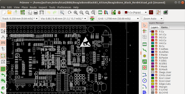
uConfig has a pretty simple premise. It scrapes manufacturer datasheets in PDF form, finds what it thinks are diagrams of parts with pin names, functions, etc, and emits the result as parts in a KiCAD library. To aid in the final conversion [Sébastien] added rules engine which consume his custom KiCAD Style Sheets which specify how to categorize pins. In the simple case the engine can string match or use regex to let you specify things like “all pins named VDD[A-C] should be power pins”. But it can also be used to move everything it thinks belongs to “GPIOB” and stick them on the bottom of the created symbol. We could imagine features like that would be of particular use breaking out gigantic parts like a 400 ball BeagleBone on a chip.

Thanks for the tip [arturo182]!

Interactive KiCAD BOMs Make Hand Assembly A Breeze

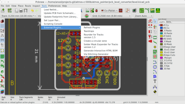
We’ve all been there; you finally get the last DigiKey box and now your desk is covered in parts to stuff into a shiny new PCB you’ve been working on. First stop? Passive town, population endless waves of 1uF capacitors. The first one goes in the upper left, then a little below that, then… once you get to C157 it’s getting pretty hard to remember exactly which parts go where. Enter the literally named InteractiveHtmlBom (IHB) to smooth this process out.

IHB makes the frustrating task of mapping lines in a BOM to a physical position on a board easy. The classic method is of course, to look at the BOM, then search the board for that designator and place the component. (You left the designators in the silk, right?) Or to look at the BOM, ask your CAD package to search for that part in the layout, then place. IHB generates a document that does this automagically.

A sample file from a familiar project

Run the tool, either standalone or as a plugin for KiCAD 5.0, and you get a folder with the new interactive BOM in it. There are a few view options but generally it presents a view of the BOM with designators and value in one pane and a wonderful render of the top and/or bottom of the board in another pane. When you hover over a BOM line it highlights the relevant parts in the board view! There are toggles for filtering by top and bottom of board, marking which parts have been placed, light and dark mode, etc. Plus the ability to filter and sort by designator and value. We would have been impressed if it was just a generator/viewer for those slick scrollable/pannable board renders!

Check out a very long GIF demo after the break, or explore one of many pre-created demo BOMs here. We’re partial to the OSPx201.

Thanks [GregDavill] for the tip!

Continue reading “Interactive KiCAD BOMs Make Hand Assembly A Breeze”

Hackaday Links Column Banner

Hackaday Links: July 29, 2018

Another holy scroll for the Church of Robotron. PoC || GTFO is a semi-annual journal of hardware exploitation, and something you must read. About a year ago, No Starch Press released the first Bible of PoC || GTFO, and now it’s time for a new testament. PoC || GTFO Volume 2 is out now, covering Elegies of the Second Crypt War to Stones from the Ivory Tower, Only as Ballast. It’s still Bible-shaped, with a leatherette cover and gilt edges.

KiCad version 5 is out, and you know what that means: It’s time to start on version 6. To that end, CERN has opened up the floodgates where youyes, you can donate to KiCad development. The team is looking for 600 hours of development and 30,000 Swiss Francs or about that many US Dollars. As of this writing (last Wednesday), more than 200 people have donated, at an average donation per person of about 80 CHF.

Oh good, this is finally over. Qualcomm will not be buying NXP. Previously, Reuters reported Qualcomm would purchase the other semiconductor manufacturer for $38 Billion, the largest semiconductor deal ever. There were earlier rumors of an acquisition. The deal was struck down by Chinese regulators, and speculation rages that this is a reaction to the US/China trade war. Qualcomm now has to pay NXP $2 Billion in fees, which they could use to dig out some of the unobtanium Motorola datasheets locked away in a file cabinet.

The uStepper (or μStepper, whatever) is a neat little add-on to standard NEMA stepper motors. It bolts to the back and gives you the ability to control a stepper over a standard serial bus, with a built-in encoder. Now there’s a new Kickstarter for an improved version that uses the Trinamic TMC2208 ‘silent’ motor driver. That Kickstarter is just a draft now, but if you’re planning a 3D printer build, this could be what you’re waiting for.