Vintage parts may be documented, but that doesn’t mean they’re particularly useful or accessible. If the phrase “eyestrain from unsearchable, badly-scanned PDF datasheets” makes your lower eyelid twitch in sympathy, read on.
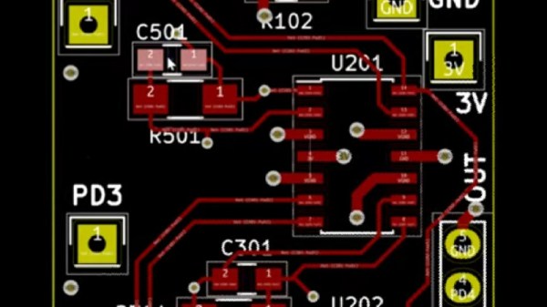
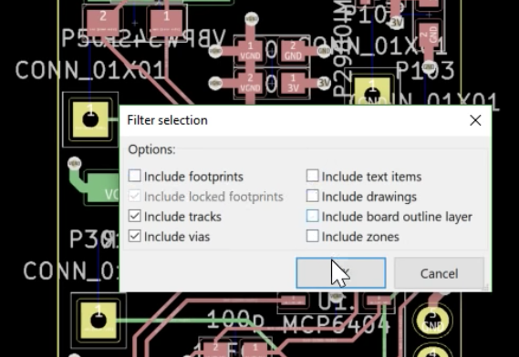
While [Bald Engineer] was researching how he might make a portable Apple II, he was delighted to find that the vintage components he needed to examine were documented. However, he became frustrated with the seemingly endless number of poor quality PDF scans and the inability to search effectively. He decided to re-create the entire Apple IIgs schematic in KiCad, and in the process the Bit Preserve project was born. The goal is to act as a safe haven for modern and editable versions of vintage electronic schematics. The GitHub repository can be found here.
[Bald Engineer] talks a bit about his Apple II project, as well as the ideas behind the Bit Preserve project in his KiCon 2019 talk “Preserving History with KiCad”. KiCon was wild, and we have loads of photos of the projects and details so be sure to check it out.