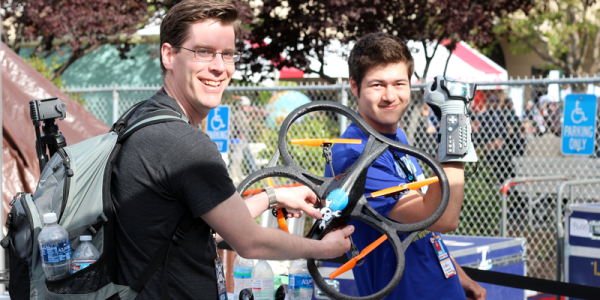
Gerrit and I were scoping out the Intel booth at Bay Area Maker Faire and we ran into Nolan Moore who was showing of his work to mash together a Nintendo Power Glove with an AR Drone quadcopter. Not only did it work, but the booth had a netted cage which Nolan had all to himself to show off his work. Check the video clip below for that.
The control scheme is pretty sweet, hold your hand flat (palm toward the ground) to hover, make a fist and tilt it in any direction to affect pitch and roll, point a finger up or down to affect altitude, and point straight and twist your hand for yaw control. We were talking with Nolan about these controls it sounded sketchy, but the demo proves it’s quite responsive.


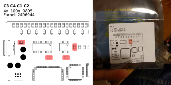
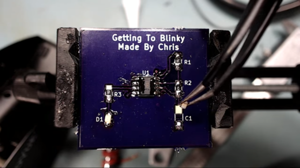
The guts of the Power Glove have been completely removed (that’s a fun project log to browse through too!) and two new boards designed and fabbed to replace them. He started off in Eagle but ended up switching to KiCAD before sending the designs out for fabrication. I really enjoy the footprints he made to use the stock buttons from the wrist portion of the glove.
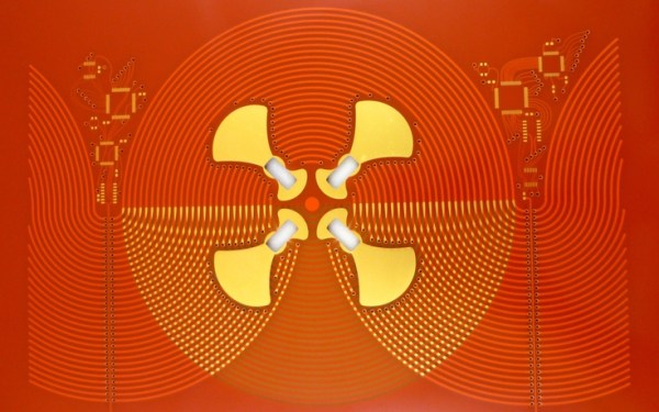
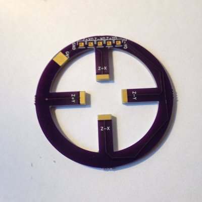
A Teensy LC pulls everything together, reading from an IMU on the board installed over the back of the hand, as well as from the flex sensors to measure what your fingers are up to. It parses these gestures and passes appropriate commands to an ESP8266 module. The AR Drone 2.0 is WiFi controlled, letting the ESP8266 act as the controller.
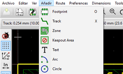 Mientras que ha habido otros intentos por localizar KiCad a otros idiomas, la mayoría de estos proyectos se encuentran incompletos. En una actualización de KiCad hace algunos meses, la localización al español ya contaba con algunas cadenas ya traducidas, pero no demasiadas. Los esfuerzos de [ElektroQuark] han acercado KiCad a millones de hablantes nativos de español, no solo algunos de sus menús.