Whether you’re a Harry Potter fan or not we think you’ll enjoy this Deathly Hallows clock. The body is modeled after the triangle, circle, and line that make up the symbol that played a prominent role when concluding the fantasy novel series. A bit of motion and a couple handfuls of LEDs are what allow it to display the time of day.
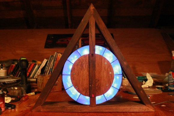
[Yeenasty] started by building the triangular surround out of wood. In the center he added a circular veneer which was partitioned into twelve chambers. These indicate the hour and are illuminated one at a time from midnight until noon. Once all of the LEDs are switched on (as seen above) they are then extinguish one at a time from noon until midnight. [Yeenasty] mentions that this means the clock isn’t overly bright during the night-time hours.
Minutes are displayed by the wooden slat in the middle of the ring of LEDs. Here it’s showing 30 minutes after the hour because it is vertical and the bottom red LED is lit. The hand is mounted on a 180 degree servo so when it has made half of a rotation the hand backtracks 29 minutes and the LED at the other end is illuminated to continue progress around the face of the clock.
[via Reddit]