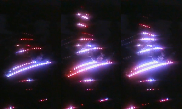
Sending The Internet From An LED Lightbulb

The number of things that can carry Internet traffic is always increasing. Now, you can add LED light bulbs to this list, as engineers in Disney Research have just demonstrated a system that transmits Internet traffic using an LED light bulb. This method of communication isn’t new: Visible Light Communication (VLC) has been demonstrated before by Disney and others, but this project puts it into a standard LED light bulb. This bulb has been modified to include an Atheros AR9331 SoC running OpenWRT and an Atmel ATmega328p that controls the LED elements and sensors that send and receive the data. So, the device is acting as a gateway between a WiFi network and a VLC one.

Disney’s new test system (PDF link) isn’t especially fast: it can only carry about 380 to 400 bits per second, so it won’t be streaming video anytime soon. That is definitely fast enough, though to send control data to a toy, or to send a continual stream of updated data to a device in the room, such as an ebook reader with a continually updated encyclopaedia. This being Disney, the authors coin a new phrase to end their paper: The Internet of Toys.

Debug An IKEA Lamp Hack, Win A Lamp Controller

[Limpkin], aka Hackaday alum [Mathieu Stephan], is at it again, converting an IKEA lamp into a visual wake-up light. He wants to build an alarm that can be remotely triggered, He’s basing this project around a combination of an ESP8266 that handles the communication and timing, and a pile of 10-watt RGB LEDs. However, he is having a problem: every time he initializes the PWM (pulse width modulation) signalling that will control the level of the LEDs, his ESP8266 dev board reboots. So, he’s offering an interesting bounty for the person who finds the issue: figure it out and he will send you the lamp. Well, the PCB and components, anyway: you’ll have to add your own IKEA lamp. It’s an interesting approach to debugging a hardware problem, so feel free to take a look. The full hardware and software details are on his GitHub repository.

LED Ring Around The ESP8266

The world needs more blinky lights, and [Bertus Kruger] has created a neat way to make lights blink wirelessly. He has a footprint in the middle of the board for soldering the castellated ESP8266 module, and an LED ring around it to create the WiFi Pixel. It’s an LED ring that can be controlled over a WiFi connection. His design is based on a combination of the ubiquitous ESP8266 WiFi chip and a NeoPixel ring from AdaFruit, so there are already great examples of how to code and control the hardware. The project is still in progress, but he has released all of the details, including the Gerber files for the board and the Arduino code that the ESP8266 is running.

It’s a great start: add in battery support and you could have an awesome way to have portable LED blinky light rings. For those who want to try it out without building your own circuit boards, [Bertus] says that it could be built with an ESP8266 dev board and an Adafruit NeoPixel ring. Currently, he is running the device from USB, but there is no reason why it couldn’t be powered from a battery for some portable USB blinkiness.

Continue reading “LED Ring Around The ESP8266”

LED Matrix Failure And Vindication

If necessity is the mother of invention, what’s failure the mother of? Improvement? Anyway, [prpplague]’s second version of his roll-up 70×30 RGB LED display looks a lot better and more reliable than the first, and that’s precisely due to “failing”.

Sometimes you design the hardware around the software, and sometimes vice-versa. It’s all about the balance of pain. [prpplague] initially wired the strips together in a consistently left-to-right raster arrangement to make the coding easier, but this means long wires on the backside of the fabric returning from the right side back to the start again at the left. These long wires snagged on stuff, and pulled the solder connections apart.

600px-Dotstar-adapter-solder3The fix? Alternate rows of left-to-right with right-to-left to minimize wiring and make nice, robust connectors for the ends, and a much more elegant implementation at the expense of more complicated software to drive the device. (Alternating rows have to be flipped horizontally, so this means custom driver routines.)

The second gremlin was that the interfacing board that [prpplague] was using didn’t have enough current sourcing capability on the SPI lines, and he discovered that he couldn’t communicate reliably with the strings if the first pixel was more than 24″ of wire away from the board. Once the signal got to the first pixel, though, everything was fine. [prpplague] figured out that the RGB LEDs themselves had more drive capability than the SPI source.

The solution? Add a single pixel at the front of the chain to buffer the SPI lines and serve as a bonus status indicator. Cute.

We’d hardly call these “fails”, but rather “learning experiences”. Anyway, here’s two design “mistakes” that we won’t make when making a roll-up flexible pixel display. Thanks [prpplague].

You Can’t Call It A Battlestation Without This Overhead Control Panel

Modern computers are rubbish. Why, they barely have a switch or a blinky light on them. What’s the point in having a computer if you don’t have the thrill of throwing a switch or eight and watching lights blink in response? [Smashcuts] obviously agrees because he built a control panel filled with heavy-duty switches and blinking wonderfulness to augment his battlestation. This piece of mechanical wonderment has buttons for useful features such as typing several levels of derisive laughter in chat windows, playing odd sound effects and a large red panic button that… well, I won’t spoil the surprise. The whole thing is hand-wired and fronted with laser-cut panels that make it look really authentic. [smashcuts] built it “because it didn’t exist and I felt like it needed to”, which is a perfect justification for this piece of industrial scale awesomeness.

It does have some more practical uses, though: he has set several of the switches to trigger actions in Photoshop and other programs, so this could be easily adapted for those who have the odd belief that things need a practical use to exist. He used USB controllers from Desktop Aviator, and a Mac program called Controller Mate to set up the sequencing for the blinkies. Unfortunately, [smashcuts] didn’t produce a how-to guide for this panel, claiming that “I don’t really have blueprints or schematics. I REALLY didn’t know what I was doing, so all the notes I do have wouldn’t make sense to anyone. It’d be like reading an owners manual to a car written by a caveman”. Either way, it is an impressive build, and you can find more details from the creator on this reddit thread.

Alcove: Blinky Art With A Killer Story

We should come clean right up front. We like blinky stuff, tech art, smoke machines, and dark atmospheric electronic music. This audiovisual installation piece (scroll down) by [supermafia] ticks off all our boxes. As the saying doesn’t really go, writing about site-specific audiovisual art pieces is like dancing about architecture, so go ahead and watch the video (Vimeo) below the break.

Continue reading “Alcove: Blinky Art With A Killer Story”

Aurora Painting

“Arduino Borealis” Combines LEDs And Paint

[Stef Cohen] decided to combine three different artistic mediums for her latest project. Those are painting, electronics, and software. The end goal was to recreate the aurora borealis, also known as the northern lights, in a painting.

The first step was to make the painting. [Stef] began with a shadow box. A shadow box is sort of like a picture frame that is extra deep. A snowy scene was painted directly onto the front side of the glass plate of the shadow box using acrylic paint. [Stef] painted the white, snowy ground along with some pine trees. The sky was left unpainted, in order to allow light to shine through from inside of the shadow box. A sheet of vellum paper was fixed to the inside of the glass pane. This serves to diffuse the light from the LEDs that would eventually be placed inside the box.

Next it was time to install the electronics. [Stef] used an off-the-shelf RGB LED matrix from Adafruit. The matrix is configured with 16 rows of 32 LEDs each. This was controlled with an Arduino Uno. The LED matrix was mounted inside the shadow box, behind the vellum paper. The Arduino code was easily written using Adafruit’s RGB Matrix Panel library.

To get the aurora effect just right, [Stef] used a clever trick. She took real world photographs of the aurora and pixelated them using Photoshop. She could then sample the color of each pixel to ensure that each LED was the appropriate color. Various functions from the Adafruit library were used to digitally paint the aurora into the LED matrix. Some subtle animations were also included to give it an extra kick.