I2C Level Converter

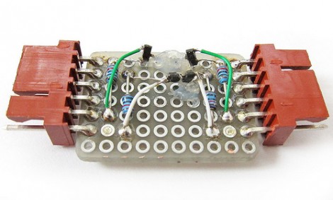
You’ve got several devices which communicate via the I2C protocol, but some of them can only operate at 3.3V while the rest are hungry for a 5V connection. What to do? [Linux-works] built this I2C level converter to solve the problem.

The circuit comes from an NXP app note (PDF) on the issue. You can take a quick peek at the suggested schematic from that document. The design uses two MOSFETS for each side of the adaptor. Perhaps a better way to explain this is that you need one for the higher voltage and one for the lower voltage on each of the two data lines for a total of four parts. This allows for both of the buses to communicate as one, while still having their own 3.3V and 5V pull-up resistors.

[Linux-works] concedes that there are chips designed to do this for you, but he was able to source the BSS138 MOSFETs locally and for about ten cents a piece. Not a bad alternative to putting in a parts order.

Reverse Voltage Protection With A P-FET

[Afroman’s] latest video shows you how to add reverse voltage protection with minimal power loss. At some point, one of your electronic concoctions will turn out to be very useful. You want to make sure that a battery plugged in the wrong way, or a polarity mistake with your bench PSU doesn’t damage that hardware. It’s easy enough to plop in a diode for protection, but as [Afroman] points out, that wastes power in the form of heat when the circuit is working correctly. His solution is to add a P channel MOSFET which only allows power to flow when the polarity of the source voltage is correct.

The schematic above shows the P-FET on the high side of the circuit. The gate is hooked to ground, allowing current to move across the DS junction when the battery is connected. This design also uses a clamping diode to keep the gate voltage within a safe range. But there are P-FETs out there that wouldn’t need that diode or resistor. This method wastes ten times less power than a simple diode would have.

We’ve embedded the video after the break where [Afroman] shares the math and reasoning behind his component choices.

Continue reading “Reverse Voltage Protection With A P-FET”

Lamp Fading And Remote Control For The Lazy

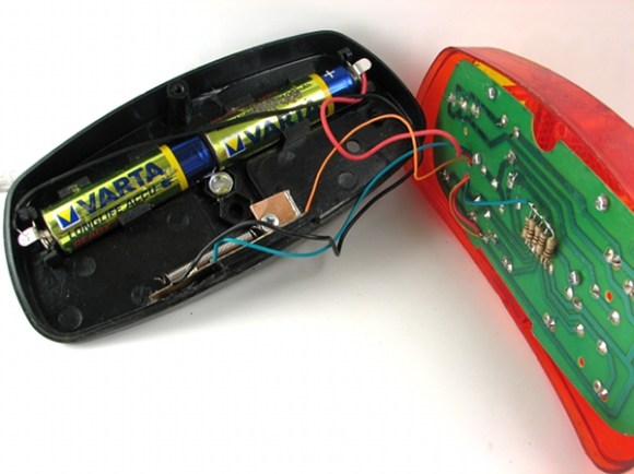
[Dmitry Grinberg] has to walk all the way across his bedroom to switch the lamp on and off. The drudgery of this finally became too much, so he built a remote control and added dimming for good measure. Above you can see the circuitry for the remote and the receiver, as well as the finished remote housed in what he calls a ‘Chinese Altoids tin’.

After the break you’ll find [Dmitry’s] demo video. The remote control is quite responsive, and the dimming has great resolution. That’s thanks to a power N-channel MOSFET which switches the AC with the help of a full wave rectifier. The PIC 12F617 that controls the MOSFET is powered separately, and [Dmitry] mentions that you must use a transformer and not a switch-mode power supply to avoid a fire. We’d like to know more about this, so leave a comment if you are able to explain further.

The remote and receiver communicate via Infrared. The protocol is operating with 38 kHz signals using an easily sourced receiver tuned to that frequency. [Dmitry] shares all the details about the encoding scheme that he uses. Recreating this communications pairing is a great way to test your understanding of this technique. But if you need a refresher, here’s a tutorial to push you in the right direction. Continue reading “Lamp Fading And Remote Control For The Lazy”

Beginner Concepts: MOSFETs

[Moser’s] introductory guide to MOSFETs serves as a quick introduction for those unfamiliar with the parts. They fill a similar role as a bipolar junction transistor like the 2N2222, making it possible to switch large loads. But fundamentally they are different. Metal Oxide Field Effect Transistors have three pins for Drain, Source, and Gate instead of the Collector, Emitter, and Base that you may be used to. The Gate is the control pin for the device and offers a desirable advantage over bipolar junction transistors in that it is insulated from the channel. This means that much less current flows into the Gate when compared to the Base of a common transistor, saving power and providing protection to the logic circuitry.

Don’t fret if this makes your head spin. [Moser’s] writeup is short and to-the-point but it’s not watered down. You can get a basic overview and if you care to learn more, he’s linked to datasheets and has basic terminology that is easily clarified with a Google search. One of the most powerful tools that he’s included is the simple MOSFET and driver circuit diagram you see above. This makes it possible to switch incredibly large loads very quickly; the true power of the MOSFET.

Laser Trip Wire – The Bare Essentials

[Gordon] sent us a tip about this simple laser trip wire system after reading yesterday’s post on a more complicated laser security unit. That build did a lot to provide functionality, such as a system to disarm the trip wire, and a robust light detection circuit. This time around there’s more happening with smoke and mirrors than with electronics.

[The Timmy] built this simpler version based on a laser trip system from Afrotechmods (video of that one is embedded after the break). He had a bag full of small square mirrors which he attached to a wall with some poster putty. A laser module shines a beam of light onto a cadmium sulfide sensor after it bounces around the optical network for a while. That CdS sensor controls an N-channel MOSFET, switching it off when light is detected and on when the intensity of the laser is absent. This example just turns an LED on and off, but since it uses logic-level voltages you can choose to add a microcontroller to the mix if you have other plans in mind.

Continue reading “Laser Trip Wire – The Bare Essentials”

$20 Fuel Injector Tester

[Dino] is an auto mechanic and needed a way to test out fuel injectors. Commercially available tools start well over $100 and go up from there, but he built his own for about $20.

The injectors have a coil in them that needs to be tested. His design calls for a series of 0.008 millisecond pulses to test the coil. He started by setting up a 555 timer to output a one second pulse. This signal is fed into a second 555 chip that outputs the 0.008 pulses and in turn actuates a MOSFET to switch the coil on and off. To use it [Dino] connects to a 12V bench supply and to the injector, using a single button to start the test. See him explain the setup in the video after the break.

Continue reading “$20 Fuel Injector Tester”

Make Your Own Solenoids, Then Play The Xylophone

Learn to manufacture your own solenoids and then use them to play the xylophone by watching the tutorial video after the break. [Humberto Evans] and the team at Nerd Kits do a great job of not only manufacturing the coils, but the xylophone itself. The bars are machined from some aluminum stock and they take you down the rabbit hole with they why’s and how’s of engineering the keys.

We’re unlikely to replicate this machining process but the solenoids are another story all together. Starting at about 3:30 you can learn about designing, building, and using these little marvels. They’re basically an electromagnetic cuff with a metal slug in the middle. The solenoid seen above uses a body milled from HDPE and wrapped with magnet wire. The slug in the center is steel, with a few rare-earth magnets at the top. When you run current through the coil it repulses the magnets on the slug, witch then strikes the xylophone key. Using a MOSFET and a protection diode, actuating them is as simple as sending a digital high from your microcontroller of choice.

We’ve seen solenoids used to play a vibrophone before, but those were commercial units. Making your own hardware is far more hardcore.

Continue reading “Make Your Own Solenoids, Then Play The Xylophone”