When we are concerned with the accurate reproduction of a signal, distortion and noise are the enemy that engineers spend a great deal of time eliminating wherever possible. However, humans being the imperfect creatures that we are, we sometimes desire a little waviness and grain in our media – typically of the analog variety, as the step changes of digital distortion can be quite painful. Tired of Instagram filters and wanting to take a different approach, [Patrick Pedersen] built the OptoGlitch – a hardware solution for analog distortion.

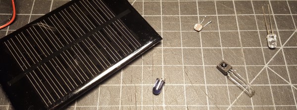
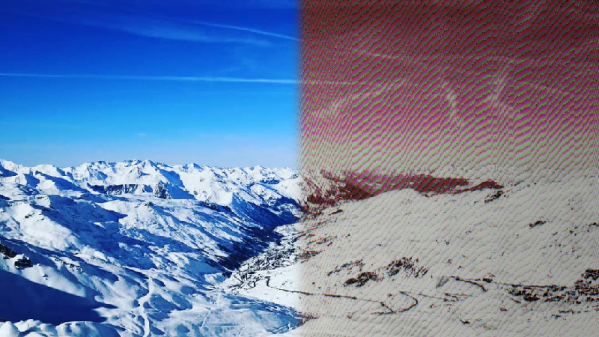
The concept of operation is simple – pixel values of a digital image are sent out by varying the intensity of an LED, and are then picked up by a photoresistor and redigitized. The redigitized image then bears a variety of distortion and noise effects due to the imperfect transmission process.
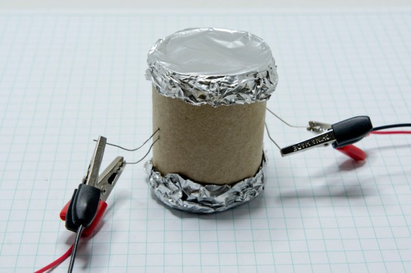
In the OptoGlitch hardware, the LED and photoresistor are intentionally left open to ambient light to further allow noise and distortion to happen during the transmission process. A variety of calibration methods are used to avoid the results being completely unrecognizable, and there are various timing and sampling parameters that can be used to alter the strength of the final effect.
It’s possible to introduce distortion more intentionally, too – such as this project that hides metadata in malformed glyphs.