DIY Optoisolator

MacGyvered Optoisolator Is A Great Introduction

Sometimes the best way to learn about a technology is to just build something yourself. That’s what [Dan] did with his DIY optoisolator. The purpose of an optoisolator is to allow two electrical systems to communicate with each other without being electrically connected. Many times this is done to prevent noise from one circuit from bleeding over into another.

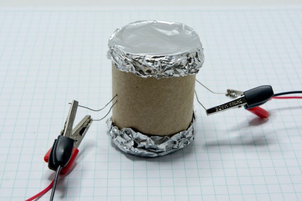
[Dan] built his incredibly simple optoisolator using just a toilet paper tube, some aluminum foil, an LED, and a photo cell. The electrical components are mounted inside of the tube and the ends of the tube are sealed with foil. That’s all there is to it. To test the circuit, he configured an Arduino to send PWM signals to the LED inside the tube at various pulse widths. He then measured the resistance on the other side and graphed the resulting data. The result is a curve that shows the LED affects the sensor pretty drastically at first, but then gets less and less effective as the frequency of the signal increases.

[Dan] then had some more fun with his project by testing it on a simple temperature controller circuit. An Arduino reads a temperature sensor and if the temperature rises above a certain value, it turns on a fan to cool the sensor off again. [Dan] first graphed the sensor data with no fan hooked up. He only used ambient air to cool things down. The resulting graph is a pretty smooth curve. Next he hooked the fan up and tried again. This time the graph went all kinds of crazy. Every time the fan turned on, it created a bunch of electrical noise that prevented the Arduino from getting an accurate analog reading of the temperature sensor.

The third test was to remove the motor circuit and move it to its own bread board. The only thing connecting the Arduino circuit to the fan was a wire for the PWM signal and also a common ground. This smoothed out the graph but it was still a bit… lumpy. The final test was to isolate the fan circuit from the temperature sensor and see if it helped the situation. [Dan] hooked up his optoisolator and tried again. This time the graph was nice and smooth, just like the original graph.

While this technology is certainly not new or exciting, it’s always great to see someone learning by doing. What’s more is [Dan] has made all of his schematics and code readily available so others can try the same experiment and learn it for themselves.

Ask Hackaday: Who Is Going To Build This Pneumatic Transmission Thing?

fluid_transmission

Disney research is doing what they do best, building really cool stuff for Disney and telling the rest of the world how cool they are. This time, it’s a very low friction fluid transmission device designed for animatronics.

From testing a few toy robotic arms, we can say without a doubt that servos and motors are not the way to go if you’re designing robots and animatronics that need lifelike motion. To fix this, a few researchers at Disney Pittsburgh have turned to pneumatics and hydraulics, where one joint is controlled by two sets of pistons. It’s extremely similar to the pneumatic LEGO, but more precise and much more lifelike.

The system uses a pair of cylinders on each joint of a robot. Disney is using a rolling diaphragm to seal the working fluid in its tubes and cylinders. This is an extremely low-friction device without any shakiness or jitters found with simple o-ring pneumatics and hydraulics.

The system is backdriveable, meaning one robotic arm can control another, and the other way around. Since we’re dealing with hydraulics, the cylinders (and robotic/animatronic devices) don’t need to be the same size; a small device could easily control a larger copy of itself, and vice versa.

The devices are fairly simple, with gears, toothed belts, and bits of plastic between them. The only unique part of these robots is the rolling diaphragm, and we have no idea where to source this. It looks like it would be great for some robotics or an Iron Man-esque mech suit, but being able to source the components will be a challenge.

You can check out the videos of these devices below, and if you have any idea on how to build your own, leave a note in the comments.

Continue reading “Ask Hackaday: Who Is Going To Build This Pneumatic Transmission Thing?”

10th Anniversary Trinket Pro Now In The Hackaday Store

Black solder mask and proudly sporting the Jolly Wrencher? The 10th Anniversary Trinket Pro boards just hit the Hackaday Store.

These were actually the suggestion of [Phil Torrone]. He founded Hackaday way back in 2004 and is now CEO of Adafruit Industries. Shortly after I asked him to record a remembrance of his time at Hackaday for the anniversary party he suggested these boards (normally blue and missing our logo) as a limited-edition for the event. It took just two weeks for them to crank out 585 of them.

I’m most likely biased for many reasons. Obviously I like putting the skull and wrenches on everything, and black solder mask is just cool. I also adore the ATmega328 (my 8-bit go-to chip for prototyping) and am especially fond of this form factor as it makes for super simple on-the-go firmware coding.

Once we sell 560 of them they will never return. We’re betting that Adafruit will have an even better minuscule breakout board for our 25th Anniversary. Do you think quantum computing will have trickled down to the single-chip prototyping stage by then?

Update: We’ve updated shipping rates on the store. Orders over $25 in the USA now have free shipping. International shipping is free for orders over $50. We will continue to try and reduce shipping rates as much as possible. We’re new to this so stay tuned!

A Mobile Radio Power Controller

[Pete], a.k.a. [KD8TBW] wanted to install his Yaesu radio in his car. From experience, he knew that having a radio in a car inevitable led to leaving it on once in a while, and this time, he wanted a device that would turn his rig on and off when the key was in the ignition. He ended up building a mobile radio power converter. It takes the 12V from the car when the alternator is running, and shuts everything off when the engine has stopped.

The Yaesu radio in question – an FT-8800 does have an automatic power off feature, but this is a terrible way of doing things. There is no way to turn the radio back on, and the radio must be left in a non-scanning mode.

In what he hopes to be his last design in EagleCAD, [Pete] whipped up a board featuring an ATtiny85 that measures the voltage in the car; when it’s ~14V, the alternator is working, and the radio can be switched on. When it drops to ~12V, it’s time to turn the radio off. It’s a great project, and with the 3D printed case, it can easily be shoved inside the console. Video below.

Continue reading “A Mobile Radio Power Controller”

Hackaday 10th Anniversary: Jon McPhalen And The Propeller

[Jon] came out to our 10th anniversary mini-con to talk about the Propeller, and judging from his short introduction, his hacker cred is through the roof. He has a page on IMDb, and his first computer was a COSMAC. Around 1993, he heard of a small company introducing the BASIC Stamp, and like us with most new technology was incredulous this device could perform as advertised. He tried it, though, and for a few years after that, he was programming the BASIC Stamp every single day.

Having a lot of blinky light project under his belt, [Jon] was always struggling with interrupts, figuring out a way to blink an LED exactly when he wanted it to blink. A lot has changed over at Parallax since 1993, and now they’re spending time with the Propeller, an 8-core microcontroller where interrupts are a thing of the past. He showed off a huge, 10-foot tall bear from League of Legends, all controlled with a single Propeller, using 1000 LEDs to look like fire and flames.

[Jon] shared the architecture of the Propeller, and the inside of this tiny plastic-encapsulated piece of silicon is wild; it’s eight 32-bit microcontrollers, all sharing some ROM and RAM, controlled by something called a Cog that gives each micro access to the address, data, and IO pins.

When the Propeller was first released, there were a few questions of how the chip would be programmed. C isn’t great for multicore work, so Parallax came up with a language called Spin. It’s written for multicore microcontrollers, and from [Jon]’s little session in demo hell, it’s not that much harder to pick up than Python. Remember that hour or two where you learned the syntax of Python? Yeah, learning Spin isn’t a huge time investment.

Even though you can program the Propeller in C and C++, there’s a reason for Spin being the official language of the Propeller. It isn’t even that hard, and if you want to dip your toes in multicore microcontroller programming, the Propeller is the way to do it. It’s an open source chip as well so you can give it a try with an FPGA board.

Thumbnail that say The Hacklet

Hacklet 18 – Tick Tock, It’s Time For Clocks

18

In three words, Hackers love clocks. Not only do we think that digital watches are still a pretty neat idea, we love all manner of timepieces. This episode of The Hacklet focuses on the clock projects we’ve found over on Hackaday.io.

xkcdHardwareWe start with [rawe] and [tabascoeye], who both put the famous XKCD “now” clock into hardware. [tabascoeye] used a stepper motor in his xkcd world clock. [rawe] didn’t have any steppers handy, so he grabbed a cheap wall clock from Ikea for his xkcd.com/now clock in hardware. The now clock needs a 24 hour movement. Ikea only sells 12 hour movements, so [rawe] hacked in a 555 and some logic to divide the clock’s crystal by two. He’s currently using an EEVblog uCurrent to verify his modified clockwork consumes about half a milliwatt.

touchscreenclockNext up is [Craig Bonsignore] and his Touchscreen Alarm Clock. [Craig] got sick of store-bought alarm clocks, so he built his own. Then he modified it, added a few features, and kept building! The current incarnation of the clock has a pretty novel interface: a touchscreen over a bicolor LED matrix. The rest of the clock consists of an Arduino, an Adafruit Wave shield, and a Macetech Chronodot. [Craig] is currently mashing up these open source designs and building a single Arduino shield for his clock.

irisledclock[Warren Janssens] took the minimalist route with The Iris Clock. Iris is a ring of WS2812 RGB LEDs. The LEDs are mounted behind a wall colored piece of wood in such a way that you can only see their glow on the clock frame and the wall beyond it. This helps a with the eye searing effect WS2812s can have when viewed directly – even when dimmed with PWM. The code is mainly C with some AVR assembly thrown in to control the LEDs. [Warren] has given Iris 8 different time modes, from hour/minute/second to percentage of day with sunrise and sunset markers. With so many modes, the only hard part is knowing how to read the time Iris is displaying!

stargate[David Hopkins] also built a ring clock. His Stargate LED Clock not only tells time, but is a great replica of the Stargate from the TV series. [David] used four Adafruit WS2812 Neopixel segments to build a full 60 RGB LED ring. The Stargate runs on an Arduino nano with a real-time clock chip to keep accurate time. A photoresistor allows the Stargate to automatically dim at night. With some slick programming [David] added everything from a visual hourly “chime” to a smooth fade from LED to LED.

bendulum[dehne1] gives us something completely different with The Bendulum Clock. A bendulum is [dehne1’s] own creation consisting of an inverted pendulum built without a pivot. The inverted pendulum swings by bending along its length. In [dehne1’s] design, the bendulum is made out of a spring steel strip rescued from a car windshield wiper. The Bendulum doesn’t have a mechanical escapement, but an electromagnet sensed and driven by an Arduino. The amazing part of this project is that  [dehne1] isn’t using a real-time clock chip. The standard 8MHz Arduino resonator is calibrated over various temperatures, then used to calibrate the bendulum itself. The result is a clock that can be accurate within 1 minute each day. [dehne1] mounted his clock inside a custom wood case. We think it looks great, and want one for Hackaday HQ!

We’ve used enough clock ticks for this episode of The Hacklet. As always, see you next week. Same hack time, same hack channel, bringing you the best of Hackaday.io!

Still want more? Check out our Timepiece List!

Beverly-Crusher, The Greatest Name For An Audio Effect

Image is © aliceazzo [http://aliceazzo.deviantart.com/].
Image © aliceazzo [http://aliceazzo.deviantart.com/].
When it comes to audio effects, you have your delay, reverb, chorus, phasing, and the rest that were derived from strictly analog processes. Compared to the traditional way of doing things, digital audio is relatively new, and there is still untapped potential for new processes and effects. One of those is the bit crusher, an effect that turns 8- or 16-bit audio into mush. [Electronoob] wanted to experiment with bitcrushing, and couldn’t find what he wanted. Undeterred, he built his own.

There are two major effects that are purely in the digital domain. The first is the sample rate reducer. This has a few interesting applications. Because [Shannon] and [Nyquist] say we can only reproduce audio signals less than half of the sample rate; if you run some audio through a sample rate reducer set to 1kHz, it’ll sound like crap, but you’ll also only get bass.

The bitcrusher is a little different. Instead of recording samples of 256 values for 8-bit audio or ~65000 values for 16-bit audio, a one-bit bitcrusher only records one value – on or off. Play it through a speaker at a decent sample rate, and you can still hear it. It sounds like a robotic nightmare, but it’s still there.

[Electronoob] created his bitcrusher purely in software, sending the resulting bitcrushed and much smaller file to an Arduino for playback. Interestingly, he’s also included the ability to downsample audio, giving is project both pure digital effects for the price of one. 1-bit audio is a bit rough on the ears, but 2, 3, and 4-bit audio starts to sound pretty cool, and something that would feel at home in some genres of music.

Continue reading “Beverly-Crusher, The Greatest Name For An Audio Effect”