Welcome back to this week’s installment of Scope Noob where I’m sharing my experiences learning to use my first oscilloscope. Last week I started out measuring mains frequency using an AC-AC wall wart adapter. Homework, for those following along, was to build a bridge rectifier and probe the signals from it. Let’s take a look.
oscilloscope295 Articles
Scope Noob: Probing Alternating Current
I finally did it. After years of wanting one (and pushing off projects because I didn’t have one) I finally bought an oscilloscope. Over the years I read and watched a ton of content about how to use a scope, you’d think I would know what I’m doing. Turns out that, like anything, hands-on time with an oscilloscope quickly highlighted the gaping holes in my knowledge. And so we begin this recurring column called Scope Noob. Each installment will focus on a different oscilloscope-related topic. This week it’s measuring a test signal and probing Alternating Current.
Measuring a Signal
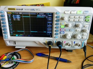
Hey, measuring signals is what oscilloscopes are all about, right? My very first measurement was, of course, the calibration signal built into the scope. As [Chris Meyer] at Sector67 hackerspace here in Madison put it, you want to make sure you can probe a known signal before venturing into the unknown.
In this case I’m using channel 2. Everything on this scope is color-coded, so the CH2 probe has blue rings on it, the probe jack has a blue channel label, and the trace drawn on the screen is seen in blue. I’m off to a fantastic start!
This scope, a Rigol 1054z, comes with an “auto” button which will detect the signal and adjust the divisions so that the waveform is centered on the display. To me this feels like a shortcut so I made sure to do all of this manually. I started with the “trigger” which is a voltage threshold at which the signal will be displayed on the screen. The menu button brings up options that will let you choose which channel to use as trigger. From there it was just a matter of adjusting the horizontal and vertical resolution and position before using the “cursor” function to measure the wave’s voltage and time.
I played around with the scope a bit more, measuring some PWM signals from a microcontroller. But you want to branch out. Because I don’t have a proper signal generator, the next logical thing to measure is alternating current in my home’s electrical system. I suppose you could call it a built-in sine wave source.
Probing Alternating Current
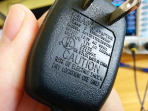
I sometimes take criticism for never throwing things away. Seven years ago we had a cat water fountain whose motor seized. It was powered by a 12V AC to AC converter seen here. Yep, I kept it and was somehow able to find it again for this project.
Of course at the time I thought I would build a clock that measures mains frequency to keep accurate time. This would have done the trick had I followed through. But for now I’m using it to protect me (and my fancy new scope) from accidental shock. I’ll still get the sine wave I’m looking for but with a source that is only 12V at 200 milliamps.
Don’t measure mains directly unless you have a good reason to do so.
Continuing on my adventure I plugged in the wall wart and connected the probe to one of the two wires coming out of it. But wait, what do I do with the probe’s reference clip? I know enough about home electrical to know that one prong of the plug is hot, the other is neutral. The clip itself is basically connected directly to mains ground. Bringing the two together sounds like a really bad idea.
This turns out to be a special case for oscilloscopes, and one that prompted me to think about writing this column. Had this been a 3-prong wall wart, connecting the probe’s reference clip to one of the wires would have been a very bad thing. Many 3-prong wall warts reference the mains earth ground on one of the outputs. If that were the case you could simply leave the clip unconnected as the chassis ground of your scope is already connected to mains ground via its own 3-prong power cord and the reference clip is a dead short to that. If you did need to probe AC using the reference clip you need an isolation transformer for your scope. There are bigger implications when probing a board powered from mains which [Dave Jones] does an excellent job of explaining. Make sure you check out his aptly named video: How NOT to blow up your oscilloscope.
As I understand it, and I hope you’ll weigh in with a comment below, since the wall wart I’m using has a transformer and no ground plug I’m fine using the ground clip of the probe in this case. Even though I’m clipping it to an AC line, the transformer prevents any kind of short between hot/neutral mains and earth ground (via the probe’s ground clip). What I don’t understand is why it’s okay to connect the transformed side of the 12V AC to mains ground?
At any rate, the screenshots above show my progress through this measurement. I first connected the probe without the ground clip and got the sad-looking trace seen on the left. After conferring with both [Adam Fabio] and [Bil Herd] (who had differing opinions on whether or not I should “float the scope”) I connected the ground clip and was greeted with a beautifully formed sine wave. I’m calling this a success and putting a notch in the old bench to remember it by.
What’s Next?
 I don’t want to get too crazy with the first installment of Scope Noob so I’ll be ending here for now. I need your guidance for future installments. What interesting quirks of an oscilloscope should a noob like me explore? What are your own questions about scope use? Leave those below and we’ll try to add them to the lineup in the coming weeks.
Homework
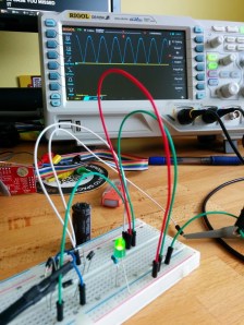
For next week I’m working my way through the adventure of rectifying this 12V AC signal into a smoothed DC source. Here you see a teaser of those experiments. I’ve built a full-wave rectifier using just four diodes (1N4001) and will plunk in a hugely-over-spec’d electrolytic capacitor to do the smoothing. If you want to follow along on the adventure you should dig around your parts drawers for these components and give it a try yourself this week. We’ll compare notes in the next post!
Easy And Effective Way To Measure PWM… Without A Scope!
Sometimes when a project is coming together, you need to cobble a tool together to get it completed. Whether it’s something very involved, like building a 3D printer to fabricate custom parts, or something relatively simple, like wiring a lightbulb and a battery together to create a simple continuity checker, we’ve all had to come up with something on the fly. Despite having access to an oscilloscope, [Brian] aka [schoolie] has come up with his own method for measuring PWM period and duty cycle without a scope, just in case there’s ever a PWM emergency!
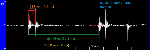
The system he has come up with is so simple it’s borderline genius. The PWM signal in question is fed through a piezo speaker in parallel with a resistor. The output from the speaker is then sent to an FFT (fast fourier transform) app for Android devices, which produces a picture of a waveform. [schoolie] then opens the picture in MS Paint and uses the coordinates of the cursor and a little arithmetic to compute the period and the duty cycle.
For not using a scope, this method is pretty accurate, and only uses two discrete circuit components (the resistor and the speaker). If you’re ever in a pinch with PWM, this is sure to help, and be a whole lot cheaper than finding an oscilloscope!
How To Get 50 More Zed From Your Rigol DS1054Z
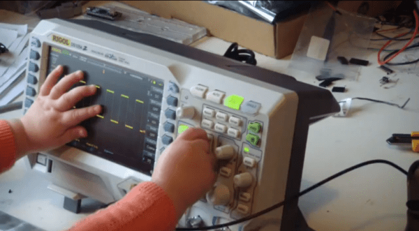
[Chris] has been spending a lot of time in the wife’s sewing room lately, and things got pretty serious late last night as he hacked his shiny new Rigol DS1054Z to unlock the 1104Z capabilities lurking within.
The rumors are true, and ungoverning the software is as simple as looking up your serial number and knowing the right URL for generating a valid license. [Chris] ran into a dud site, but that’s the price of doing business in the shadowy parking garage basements of the interwebs. Once he knocked on the right door and uttered the secret word, however, he became the proud owner of 50MHz additional bandwidth, decoders for SPI, I²C, and RS-232, twice the storage depth, and all teh triggers that ship with the 1104Z.
Can’t rationalize the purchase even at the ridiculously low price point? Here’s one way to make it happen. You’ll laugh, you’ll cry, you’ll learn some French.
Continue reading “How To Get 50 More Zed From Your Rigol DS1054Z”
Hardware “Security” And A DMCA Takedown Notice
 Last week we published a post about how it was discovered through trial and error that Tektronix application modules are designed with laughable security. We’ll get to that part of it in a minute. We received a DMCA Takedown Notice from Tektronix (which you can read after the break) demanding that we remove the post. We have altered the original post, but we believe our coverage of this story is valid and we don’t agree that the post should be completely removed.
First off, Tektronix sells the modules to unlock the features already present on the Oscilloscope in questions. We’re operating on the moral assumption that using these features without paying their asking price is wrong. If you want the features they’ve developed you should pay for them.
The real story here is that Tektronix designed a woefully weak system for unlocking these modules. Learn from this. If you’re ever designing a hardware key, don’t do it like this!
An EEPROM, a connector, and a plain text string of characters which is already published publicly on their website is all that is necessary to unlock these “crippled” features. Let’s just say that again: apparently every hardware key is the same and just uses a plain-text string found on their website which is not encrypted or obfuscated. If you were selling these keys for $2.99 perhaps this would be adequate, but Tek values these modules at $500 apiece.
If you were designing this system wouldn’t it be worth using an encryption key pair based on the serial number or some other piece of unique information? How do you think this should have been done? Leave your comment below.
Continue reading “Hardware “Security” And A DMCA Takedown Notice”
Cloning Tektronix Application Modules
Tektronix’s MSO2000 line of oscilloscopes are great tools, and with the addition of a few ‘application modules’, can do some pretty interesting tasks: decoding serial protocols, embedded protocols like I2C and SPI, and automotive protocols like CAN and LIN. While testing out his MSO2012B, [jm] really liked the (limited time) demo of the I2C decoder, but figured it wasn’t worth the $500 price the application module sells for. No matter, because it’s just some data on a cheap 24c08 EEPROM, and with a little bit of PCB design <<removed because of DMCA takedown>>
The application module Tektronix are selling is simply just a small EEPROM loaded up with an <<removed because of DMCA takedown>>. By writing this value to a $0.25 EEPROM, [jm] can enable two applications. The only problem was getting his scope to read the EEPROM: a problem easily solved with a custom board.
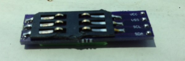
The board [jm] designed <<removed because of DMCA takedown>>, with the only additional components needed being an EEPROM, a set of contacts for reading a SIM card, and a little bit of plastic glued onto the back of the board for proper spacing.
UPDATE: Learn about the DMCA Takedown Notice that prompted this post to be altered: http://hackaday.com/2014/08/05/hardware-security-and-a-dmca-takedown-notice/
A Most Impractical Gear Position Indicator
 A few years ago, [Pat] sent in a really nice gear position indicator for his Suzuki V-Strom. With a single seven-segment display , a small microcontorller, and wires tied right into the bike’s ECM, it’s more than enough to do its job, and is much cheaper than aftermarket gear indicators. A simple, elegant solution that does one job well. How could this possibly be any better?
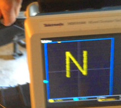
‘Better’ is a relative term, and depending on what you’re optimizing for, a more complex solution can easily be superior. [Pat] figured tripling the value of his motorcycle is a worthwhile goal, so he replaced that seven-segment display with an oscilloscope. It’s the world’s only oscilloscope based motorcycle gear position indicator, and now [Pat] needs a really, really long extension cord.
Like the earlier, more practical version, This build reads the voltage off the bike’s ECM to determine what gear the bike is in. The current gear is then displayed on a Tek MDO3000 with two PWM pins on a microcontroller. Practical? No, but it does look cool. Video below.
Continue reading “A Most Impractical Gear Position Indicator”

