Philips Lamp Upgrade

Increasing The Brightness Of A Philips LivingColors Lamp

[Martin] recently purchased a Philips LivingColors lamp. It’s a commercial product that basically acts as mood lighting with the ability to change to many different colors. [Martin] was disappointed with the brightness of his off-the-shelf lamp. Rather than spend a few hundred dollars to purchase more lamps, he decided to modify the one he already had.

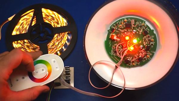
[Martin] started by removing the front cover of his lamp. He found that there were four bright LEDs inside. Two red, one green, and one blue. [Martin] soldered one wire to the driver of each LED. These wires then connected to four different N-channel MOSFET transistors on a piece of protoboard.

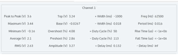
After hooking up his RIGOL oscilloscope, [Martin] was able to see that each LED was driven with a pulse width modulated signal. All he had to do was connect a simple non-addressable RGB LED strip and a power source to his new driver board. Now the lamp can control the LED strip along with the internal LEDs. This greatly extends the brightness of the lamp with minimal modifications to the commercial product. Be sure to check out the video below for a complete walk through. Continue reading “Increasing The Brightness Of A Philips LivingColors Lamp”

Controlling A Rigol With Linux

The Rigol DS1052E is the de facto oscilloscope for any tinkerer’s bench. It’s cheap, it’s good enough, and it’s been around for a long time; with the new 1054 zed model out now, you might even be able to pick up a 1052E on the cheap.

[wd5gnr1] came up with a really interesting piece of software that allows a Linux system to control most of the functions on this popular scope. With just a USB cable, you can read and log all the measurement of the scope, save waveforms in CSV format, and send data to gnuplot and qtiplot.

Since the 1052E has been around for such a long time, there’s a bunch of software out there that takes advantage of the nifty USB port on the front of this scope. If you need a cheap spectrum analyzer, here ‘ya go, and tools for the .WFM files native to this scope even exist for Windows. [wd5gnr1] even says his tool can probably be ported to Windows, but ‘just use Linux.’

Nerdalert: German TV Producers’ Amazing Vectorscope Animations

German weekend late-night comedy show “Neo Magazin Royale” has a bunch of super-nerds behind the screens in the production studio. This is apparently what they do when they’re (not) working: making test screens that render as multiple animations on their test equipment.

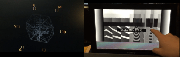
While others out there are limited to displaying cool graphics on oscilloscopes, these guys have vectorscopes and waveformer monitors. A vectorscope is like an oscilloscope in X-Y mode, but with one screen that decodes the color space and one screen for the audio (in stereo). A waveform monitor that plots out the brightness levels of a test image. Normal studio techs use these to calibrate their colors, brightness, and audio levels.

Apparently, these guys programmed a custom test screen that would: a) encode a small animation of a 20-sided die spinning around the show’s logo in the color channel b) encode the show’s logo in the left and right sound channels, and c) their production company’s logo in the screen’s brightness.

At the end of the video, the director Patrick (in the glasses) admits that they’ve spent about three months working on this project and everyone starts laughing. “And who gets anything from this? Nobody!” says the show’s host.

One way to rectify that, though. Post the source code!

Hacklet 36 – Oscilloscope Projects

Oscilloscopes are one of the most often used tools of the engineer, hacker, or maker. Voltmeters can do a lot, but when you really need to get a good look at a signal, a good scope is invaluable. This week’s hacklet is triggered by the rising slope of some of the best Oscilloscope projects on Hackaday.io!
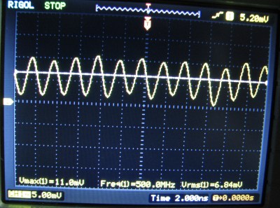
rigol500We start with [DainBramage’s] recent project Stretching the Limits of a Rigol DS-1102E Scope. The new Rigol ds1054z may be getting all the press lately, but the older DS-1102E (100 MHz) model is still a very capable scope. [DainBramage] broke out his vintage Singer CSM-1 service monitor to generate frequencies all the way up to 500 MHz. The Rigol did admirably well, detecting a sine wave all the way up to 500 MHz. This is in part due to the scope’s 1 gigasample-per-second sampling rate. Once things got beyond the specified limit of 100 MHz though, the signal began to attenuate.  Not bad for pushing a low-end scope way beyond its limits!
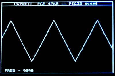
 

cornel-scopeNext up is [Bruce Land] with his PIC32 oscilloscope. Microcontroller scope projects are nothing new, but one that runs at nearly 1 MHz sampling rate while generating NTSC composite video is nothing to sneeze at. [Bruce] pulled this off by using Direct Memory Access (DMA) to move the data from the ADC to memory, and to get the video data from memory to the I/O pins used to generate video. The video itself is created by a resistor tree DAC. All you need to make black and white video is three resistors and two I/O pins. [Bruce] says the entire scope cost about $4.00 us in parts!
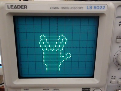
scope-hand[Jacob Christ] mixed art and science with his chipKIT Oscilloscope Plotter. [Jacob] used a Microchip PIC32 based Fubarino to draw patterns on his scope. To do this the scope must be set to X-Y mode. [Jacob] paired his Fubarino with a MCP4902 Digital to Analog Converter (DAC). Using a dedicated DAC is a great way to do this. [Jacob’s] images are a testament to that, as they’re some of the cleanest “scope art” drawings we’ve seen. Much like [Bruce Land], [Jacob] used his project as the basis for a college class. In fact, the image to the left was created by one of his students!

Want more scope goodness? Check out our new Oscilloscope Projects List!

Hackaday.io Update!

Hackaday.io is getting new features every day. Our dev team has just rolled out a new gallery view. Just click on a project’s featured image, or the “View Gallery” button, and you will be taken to a gallery view of every image used in the project – including log images. YouTube videos will render in the gallery as well. It’s a great way to view a timeline of progress for some of the projects on hackaday.io. For a great example of this, check out OpenMV’s gallery.

In other Hackaday.io news, check out the Caption CERN Contest! Every week we put up a new image from CERN’s archives. The Hackaday.io user who comes up with the funniest caption wins a T-Shirt from The Hackaday Store!

Looks like we’ve hit the end of the trace for this Hacklet. Same hack time, same hack channel, bringing you the best of Hackaday.io!

Reverse Engineer Then Drive LCD With FPGA

Fans of [Ben Heck] know that he has a soft spot for pinball machines and his projects that revolve around that topic tend to be pretty epic. This is a good example. At a trade show he saw an extra-wide format LCD screen which he thought would be perfect on a pinball build. He found out it’s a special module made for attaching to your car’s sun visor. The problem is that it only takes composite-in and he wanted higher quality video than that offers. The solution: reverse engineer the LCD protocol and implement it in an FPGA.

This project is a soup to nuts demonstration of replacing electronics drivers; the skill is certainly not limited to LCD modules. He starts by disassembling the hardware to find what look like differential signaling lines. With that in mind he hit the Internet looking for common video protocols which will help him figure out what he’s looking for. A four-channel oscilloscope sniffs the signal as the unit shows a blue screen with red words “NO SIGNAL”. That pattern is easy to spot since the pixels are mostly repeated except when red letters need to be displayed. Turns out the protocol is much like VGA with front porch, blanking, etc.

With copious notes about the timings [Ben] switches over to working with a Cyclone III FPGA to replace the screen’s stock controller. The product claims 800×234 resolution but when driving it using those parameters it doesn’t fill the entire screen. A bit more tweaking and he discovers the display actually has 1024×310 pixels. Bonus!

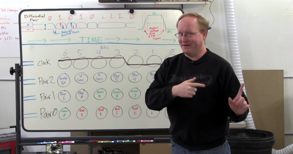
It’s going to take us a bit more study to figure out exactly how he boiled down the sniffed data to his single color-coded protocol sheet. But that’s half the fun! If you need a few more resources to understand how those signals work, check out one of our other favorite FPGA-LCD hacks.

Continue reading “Reverse Engineer Then Drive LCD With FPGA”

Save Data From Old Scopes With A GPIB Disk Emulator

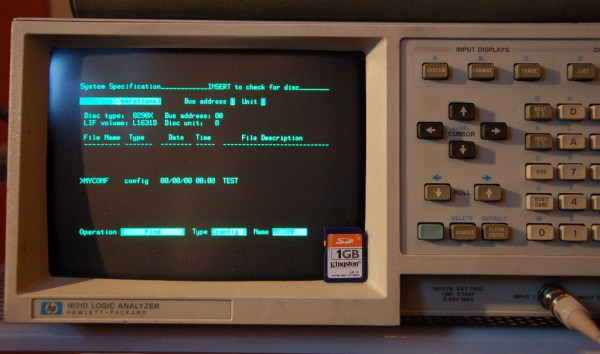
If you still use old test equipment on a regular basis, you probably have been frustrated by the lack of options for pulling data off these aging devices. Many higher-end devices are equipped with GPIB ports, which are general purpose buses for communicating with a variety of obsolete peripherals. Since GPIB disk drives aren’t too common (or practical) these days, [Anders] made a GPIB adapter that emulates a disk drive and stores data to an SD card.

[Anders] designed a PCB with a PIC microcontroller that plugs into a GPIB port. The PIC emulates a disk drive using the AMIGO protocol or the SS/80 protocol, which can be selected in a configuration file on the SD card. Most test equipment supports one of these two protocols, so his adapter should work with pretty much any GPIB-equipped kit.

Data is saved to a single image file on the SD card, which is encoded in a native HP disk format. The image file can be opened on Windows and Linux with some utilities that [Anders] mentioned on his project page. If you have any old test equipment withGPIB lying around and want to build your own, the schematic and source code are up on his site or [Anders] is selling bare boards.

Now if it’s a protocol converter that you need we’ve seen those in a couple of different varieties.

Ultimate Oscilloscope Hack – Quake In Realtime

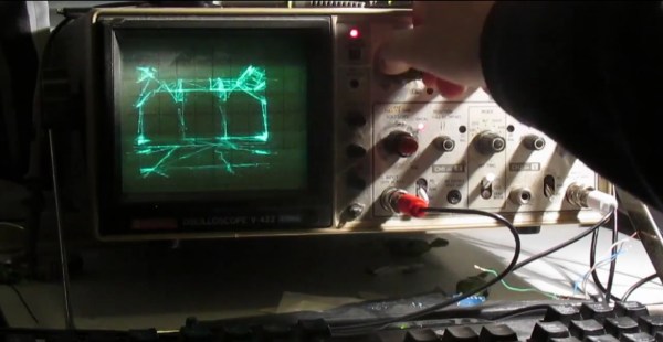
[Pekka] set himself up with quite the challenge – use an oscilloscope screen to display Quake in realtime – could it even be done? Old analog scope screens are just monochromatic CRTs but they are designed to draw waveforms, not render graphics.

Over the years Hackaday has tracked the evolution of scope-as-display hacks: Pong, Tetris, vector display and pre-rendered videos. Nothing that pushed boundaries quite like this.

[Pekka]’s solution starts off the same as many others, put the scope in X-Y mode and splice up your headphone cable – easy. He then had to figure out some way to create an audio signal that corresponded to the desire image. The famous “Youscope” example demos this, but that demo is pre-rendered. [Pekka] wanted to play Quake in realtime on the scope itself, not just watch a recording.

With only so much bandwidth available using a soundcard, [Pekka] figured he could draw a maximum of about a thousand lines on screen at a time. The first headache was that all of his audio cards had low-pass filters on them. No way around it, he adjusted his ceiling accordingly. ASIO and PortAudio were his tools of choice to create the audio on the fly from a queue of XY lines given.

To tell his audio engine what lines to draw, he solicited Darkplaces – an open source Quake rendering engine – and had it strip polygons down to the bare minimum. Then he had to whip out the digital hedge trimmers and continue pruning. This writeup really cannot do justice to all the ingenious tricks used to shove the most useful data possible through a headphone jack. If this kind of thing interests you at all, do yourself a favor and check out his well-illustrated project log.

In the end [Pekka] was not entirely happy with the results. The result is playable, but only just barely. The laptop struggles to keep it simple enough, the soundcard struggles to add enough detail and the scope struggles to display it all quickly enough. At the very least it sets the bar extraordinarily high for anyone looking to one-up him using this method. There is only so much water that can be squeezed from a rock.

See the video below of [Pekka] playing the first level of Quake.

Continue reading “Ultimate Oscilloscope Hack – Quake In Realtime”