Fail Of The Week: Motorizing A PCB Cutting Shear

This week’s fail is an attempt to retrofit a PCB cutting shear with a geared motor. The project was undertaken by [David Cook]. Incidentally he’s very near and dear to us as his book Robot Building for Beginners got us started with hacking in the first place.

This $200 shearing tool is hand-operated and can cut through boards up to 1/16″ thick. But [David] really had to crank on the thing to make a cut. This often resulted in crooked board edges. He decided to do the retrofit in order to achieve higher precision. He sourced a high-torque motor from eBay for around $50 delivered.

Continue reading “Fail Of The Week: Motorizing A PCB Cutting Shear”

Rock Solid PCB Mill Built At Home

Let’s all slow clap for [Daniel Taylor] who, after a long journey, got his home built PCB mill up and running with remarkable precision. That’s 10 mil traces with 0.5mm pitch pads. We’re impressed! The board will be used for breaking out the connections of an LCD screen he has on hand.

After seeing a CNC project as yesterday’s Fail of the Week it’s nice to look in on one like this that does some amazing stuff. In fact, [Daniel’s] creation has been working for months already. The link above is the project log he kept while hacking, tweaking, and retrofitting his rig to get the level of precision he was after.

Improvements include swapping out drawer slides for proper linear bearings and completely reworking the Z-axis along with a motor upgrade. For those that aren’t fans of the reading (how did you make it this far into this feature?) you can take a quick look at his image gallery which includes captions.

Drilling PCBs With Cameras And Math

PCB

After making your first PCB, you’re immediately faced with your next challenge – drilling the holes. It’s a doable task with a small drill press, but a lot of makers already have a small CNC mill or router, but how to make that work the first time? [Alessio] has you covered with a technique that uses a CNC-mounted webcam and some linear algebra for perfect through-holes the first time and every time.

A few months ago we saw [Alessio]’s work with transform matrices and PCB drills. The reasoning behind this technique is if a PCB isn’t exactly aligned to a CNC mill’s axes, or if the scaling for a toner transfer board is a bit off, automating the drilling process will only end in pain, with holes going through traces and a whole host of other nasty things. The application of linear algebra gets around this problem – taking a measurement off of two or three known locations, it’s easy to program a CNC machine to drill exactly where it’s supposed to.

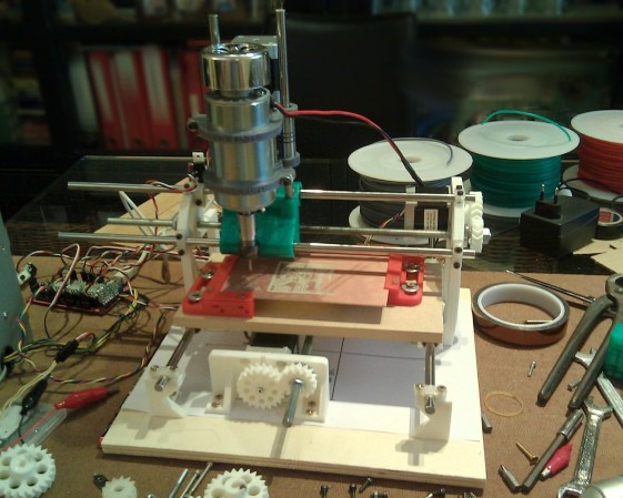
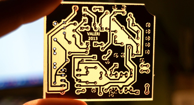
[Alessio]’s new project takes the same mathematical techniques and applies them to a very sleek application that uses a drill-mounted webcam. After taping his homebrew PCB down to the mill, [Alessio] simply marks off a few known points, imports the drill file, and lets a computer calculate where to drill the holes. The results are remarkable – with a soldermask and silkscreen equipment, these handmade boards can be just as good as professionally manufactured boards,

There are Windows and OS X binaries for [Alessio]’s tool available on his page, with a video demo available below.

Continue reading “Drilling PCBs With Cameras And Math”

OSH Park Adds Board Sharing Feature

osh-park-board-sharing

OSH Park continues to get better and better. We think the recent addition of Project Sharing is a huge feature! Obviously this lets you order up the open source goodness posted by others with a minimum amount of effort. But to us there are a couple of other things that make this valuable.

First off, the ability to browse through the projects can be a huge inspiration for your own work. Secondly, the board files themselves are available for download, and it looks like you can post links to your repository if you so choose when sharing your project. This makes OSH Park something of a Thingiverse for PCBs. Browse through what’s offered then download the files to etch yourself or just to use as reference to see how others do things when laying out the traces. And of course the rock bottom prices offered make this a no-brainer for shared breakout board designs.

The Twitter post calls this the “early stages” of the feature. We can’t wait to see what they come up with as it matures.

PCBs With Powder Coat

pcb

The toner transfer method of PCB production should be a staple in every maker’s bag of tricks. That being said, it’s a far from ideal solution with a lot of things that can go wrong, ruining hours of work. [Ryan] thinks he has a better solution up his sleeve, still using heat activated toner, but replacing the laser printer with a powder coating gun and a laser engraver.

[Ryan] is using a powder coating gun he picked up from Amazon for about $100. The theory behind it is simple: particles of toner coming out of the gun are statically charged, and bonded to the grounded copper clad board. In real powder coat shops, this coating is baked, resulting in a perfectly hard, mirror-like finish. [Ryan] skipped the baking step and instead through the powder coated board into a laser engraver where the PCB design is melted onto the copper. After that, wash the board off, etch it, and Bob’s your uncle.

What’s really interesting about this method of PCB production is that it doesn’t require a very high power laser. [Ryan] was actually having a problem with the toner burning with his laser engraver, so it might be possible to fab PCBs with a high power handheld laser, or even a Blu Ray laser diode.

Cyclone PCB Factory: 3d Printable Circuit Board Mill

printable-cyclone-pcb-factory

If you can 3D print most of the parts for another 3D printer, why not also for a PCB mill? That’s the question answered by the Cyclone PCB Factory. It will help you kiss those toner transfer or photo resist days goodbye.

Homemade circuit boards tend to be rather small, which really helps keep the cost and scope of this project down. Most of the mounting parts, as well as the gears, are 3D printed. Of course there’s the usual machine tool items which you pretty much have to purchase: the ball screws, precision rod, stepper motors, and a motor to spin the routing tool.

Check out the video below to see where the project is right now. One of the crucial aspects of PCB milling is to have a level build table. The cutter head tends to be ‘V’ shaped so cutting just a bit too deep can blow out the traces you’re trying to isolate. The demo shows that this can automatically calibrate the software to account for any variances in the height of the copper clad.

We remember seeing a snap-together PCB mill. But we’re pretty sure that that one used parts milled from HDPE rather than 3D printed components.

Continue reading “Cyclone PCB Factory: 3d Printable Circuit Board Mill”

Making PCBs And Waffles

waffle

The toner transfer method of fabricating PCBs is a staple in every maker’s toolbox. Usually, tutorials for this method of making PCBs rely on a clothes iron or laminating machine. They work perfectly well, but with both of these methods (sans high-end laminators), you’re only heating one side of the board at a time, making perfect double-sided PCBs somewhat of a challenge.

[Mark] just came up with an interesting solution to this problem. A waffle iron PCB press. Technically, [Mark] is using his ‘grill and waffle baker’ as a two-sided griddle, with a few aluminum plates sandwiching the copper board for good thermal conduction.

After a whole lot of trial and error, [Mark] eventually got a good transfer onto a piece of copper clad board. Now that he has the process dialed in, it should be a snap to replicate his results with a new project and a new PCB design.