EagleUp Pulls Your PCBs Into SketchUp

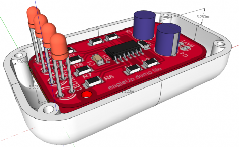
[Karl] wrote in to tell us about a software package called EagleUp that will import your Eagle CAD PCB designs into Google SketchUp. It bridges the gap between the two using the open source image processing software ImageMagick.

As you can see above, you’ll end up with a beautifully rendered 3D model of your hardware. This is a wonderful way to make sure that your enclosure designs are going to work without needing to wait for the PCBs to arrive from the fab house. It is available for Windows, OSX and Linux (although the last time we tried to run Sketchup under Wine nothing good came of it — perhaps it’s time to try again).

In [Karl’s] case, he’s working on an Arduino compatible board based around the Xmega. He mentions that EagleUp is a great way to get an idea of how component placement will end up, and to see if the silk screen layer is going to turn out well or not. Here’s a link to one of his test designs.

CadSoft’s EAGLE 6 Hits Beta And Packs Goodies

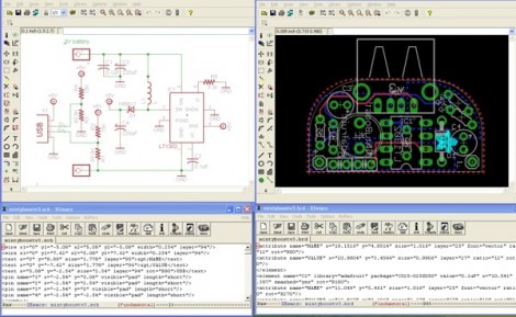
Version 6 of the popular schematic and PCB layout software EAGLE is now in beta testing. The most notable change is the migration to XML file formats that we looked at last month.

[PT] didn’t waste any time getting his hands on the software and giving it a thorough test drive. The image seen above shows the files of a MintyBoost. It’s impossible to make out at this resolution, but it is indeed spitting out human-readable (well maybe) XML in the windows below instead of the ‘no trespassing’ binaries they used to use.

Earlier today when working on a feature we had to jump on a different computer that had EAGLE installed in order to look at a .SCH file. We wonder if someone will put out a rendering package that can parse the new format and spit out a quick PNG? At the very least, we expect to see some useful hacks for part replacement or pin swapping. It shouldn’t be too hard to poke around and figure out what happens when changing some of the stored values. Got anything in mind that you can do by editing these by hand?

Oh, we almost forgot! The biggest benefit you get from this is the increased version control compatiblity since programs like git will be able to perform diff functions on the files.

LCD Backpack: From Arduino Board To Homemade Pcb

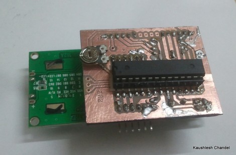
[Kaushlesh Chandel] prototyped a few projects on his Arduino that use an HD44780 Character LCD. Wanting to keep these projects in one piece, but not sacrifice his Arduino board, so he etched his own LCD backpack that is Arduino compatible. If you’ve never made it past the Arduino board to build a module that only uses the parts you need for a project, this is a great source of inspiration for you to give it a try.

The design that [Kaushlesh] drew up is quite simple. It connects directly to the single in-line header of the character LCD. It looks like he’s using the 4-bit mode for addressing that display, which leaves you with quite a few pins (both digital and analog) to work with in the future. The important components rolled into his design are the chip itself, an ATmega8/168/328, the crystal to make sure it is running at the correct speed for Arduino timing, and a trimpot for adjusting the contrast on the display. The final feature you’ll want to be sure to include in your own design is a pin header for programming the chip via an FTDI cable.

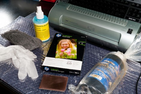
Never etched your own PCB before? Give our PCB fab tutorial a try.

Modding An Inkjet For PCB Production

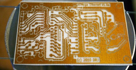
Like all of us, [Ryan] is tired of waiting for board production houses. To reduce some of that turnaround time, he modded an Epson inkjet into a PCB printer. The Instructable of his build is extremely thorough and it looks like he’s getting some quality boards out of his project

The build started off by disassembling an Epson C86 printer he had lying around the house. Going with an Epson printer is important – Epsons have a piezo print head accepts ink that would clog other printers. After tearing all the plastic off his printer, [Ryan] set to work raising the printer (or lowering the bed, whatever) and was off to the races.

The cartridges were filled with etch-resistant yellow ink and a piece of copper clad put onto the printer. After printing, [Ryan] etched his board in ferric chloride. Sadly, he’s getting small pinholes in his traces where a bit of the ink was eaten during etching. He’s tried HCl and Peroxide, but those turn his boards into green junk.

If you’ve got any tips to help [Ryan] out, leave them in the comments. Before that, check out the printing demo [Ryan] put up.

Continue reading “Modding An Inkjet For PCB Production”

PCB Drill From R/C Car Parts

[Sid] makes a few PCBs a month and the hardest part of his fabrication process is always drilling the through-holes. He has a PCB hand drill that usually results in a sore index finger. After a few unsuccessful attempts of using a full-size electric drill and not wanting to invest in a commercial solution, [Sid] made a PCB drill from a broken R/C car.

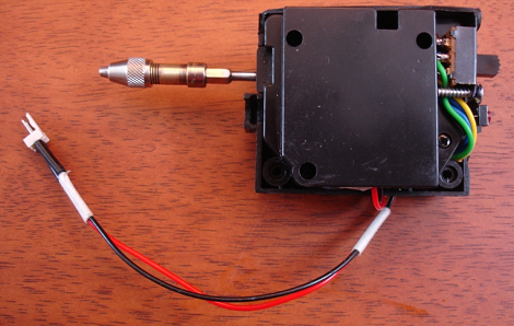
The toy car was donated by [Sid]’s 4-year-old after a terrible crash. [Sid] took the gearbox from the car and added a small circuit to control the direction of the drill. After attaching the drill chuck to the former R/C car axle and adding the power leads to a 5 Volt adapter, a PCB drill press was born.

Most of the parts for this build were salvaged from the toy car’s radio control circuit. Except for the chuck from [Sid]’s hand drill and a few switches, everything on this build was pulled from a broken remote control car. While the build is a lot simpler than this semi-automatic PCB drill, [Sid]’s drill seems to work well. Check out the demo video after the break.

Continue reading “PCB Drill From R/C Car Parts”

Laser Etched PCB Production

Like most of us, [reonarudo] isn’t satisfied with the current methods of homebrew PCBs, so he put a laser on a reprap and started burning some boards.

The basic procedure is to cover a copper clad board with matte black spray paint. A laser was installed on the X carriage of the reprap. [reonarudo] used cad.py to convert the board files into g-code and fired up his laser. The quality of the boards is highly dependent on the accuracy of the laser so after working through some mechanical problems [reonarudo] managed to make some passable boards.

We’ve seen just about every manufacturing method imaginable applied to PCB production. Etch resist and toner transfer do the job and a reprap milling machine is pretty neat, but lasers are so much cooler. While it may not be perfect (yet), printing PCBs with a laser shows a lot of potential. Check out a video of [reonarudo]’s bot burning some copper after the break.

Continue reading “Laser Etched PCB Production”

This Marriage Proposal Is The Best PCB Design Ever

best_pcb_design_ever

While you will often see hacks on this site that feature high voltage, fire, and metal, that doesn’t mean that hackers, makers, and electronics geeks don’t have a soft side. In fact, we find the opposite to be true the vast majority of the time.

Take for instance [Bill Porter].

You may have seen his projects and tutorials featured here a time or two, and though I have never met him, he seems like a great guy whose heart is in the right place.

He recently decided that his college sweetheart was “the one” and had to think of a clever and surprising way to pop the question to a girl who is always one step ahead of the curve. [Mara (soon to be) Porter] was working on a project that required a custom PCB, and having never ordered one before, [Bill] was happy to help her get things in order. After sending the schematics off to [Laen] at DorkbotPDX, [Bill] fired off another email asking to have his proposal silk screened on the boards. [Laen] said he was happy to help, and so the wait began.

The boards arrived a few weeks later, and the rest, they say, was history.

How did it go? We’re guessing you’ve figured it out by now, but be sure to swing by [Bill’s] site to see how it all went down.

You know you want to…you big softie!