PCB Dielectric Constant Measurements, Three Ways

FR4 is FR4, right? For a lot of PCB designs, the answer is yes — the particular characteristics of the substrate material don’t impact your design in any major way. But things get a little weird up in the microwave range, and having one of these easy methods to measure the dielectric properties of your PCB substrate can be pretty handy.

The RF reverse-engineering methods [Gregory F. Gusberti] are deceptively simple, even if they require some fancy test equipment. But if you’re designing circuits with features like microstrip filters where the permittivity of the substrate would matter, chances are pretty good you already have access to such gear. The first method uses a ring resonator, which is just a PCB with a circular microstrip of known circumference. Microstrip feedlines approach but don’t quite attach to the ring, leaving a tiny coupling gap. SMA connectors on the feedline connect the resonator to a microwave vector network analyzer in S21 mode. The resonant frequencies show up as peaks on the VNA, and can be used to calculate the effective permittivity of the substrate.

Method two is similar in that it measures in the frequency domain, but uses a pair of microstrip stubs of different lengths. The delta between the lengths is used to cancel out the effect of the SMA connectors, and the phase delay difference is used to calculate the effective permittivity. The last method is a time domain measurement using a single microstrip with a couple of wider areas. A fast pulse sent into this circuit will partially reflect off these impedance discontinuities; the time delay between the reflections is directly related to the propagation speed of the wave in the substrate, which allows you to calculate its effective permittivity.

One key takeaway for us is the concept of effective permittivity, which considers the whole environment of the stripline, including the air above the traces. We’d imagine that if there had been any resist or silkscreen near the traces it would change the permittivity, too, making measurements like these all the more important.

Continue reading “PCB Dielectric Constant Measurements, Three Ways”

Just How Good Is A Tape Measure Antenna Anyway?

Amateur radio operators have played a longstanding game of “Will It Antenna?” If there’s something even marginally conductive and remotely resonant, a ham has probably tried to make an antenna out of it. Some of these expedient antennas actually turn out to be surprisingly effective, but as we can see from this in-depth analysis of the characteristics of tape measure antennas, a lot of that is probably down to luck.

At first glance, tape measure antennas seem to have a lot going for them (just for clarification, most tape measure antennas use only the spring steel blade of a tape measure, not the case or retraction mechanism — although we have seen that done.) Tape measures can be rolled up or folded down for storage, and they’ll spring back out when released to form a stiff, mostly self-supporting structure.

But [fvfilippetti] suspected that tape measures might have some electrical drawbacks, thanks to the skin effect. That’s the tendency for current to flow on the outside of a conductor, which at lower frequencies on conductors with a round cross-section turns out to be not a huge problem. But in a thin, rectangular conductor, a little finite element method magnetics (FEMM) analysis revealed that most of the current is carried in very small areas, resulting in high electrical resistance — an order of magnitude greater than a round conductor. Add in the high permittivity of the carbon steel material of the blade, and you end up something more like what [fvfilippetti] calls “a tape measure dummy load.

One possible solution: stripping the paint off the blade and copper plating it. It’s not clear if this was tried; we’d think it would be difficult to accomplish, but not impossible — and surely worth a try.

Can You 3D-Print A Stator For A Brushless DC Motor?

Betteridge’s Law holds that any headline that ends in a question mark can be answered with a “No.” We’re not sure that [Mr. Betteridge] was exactly correct, though, since 3D-printed stators can work successfully for BLDC motors, for certain values of success.

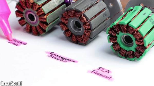
It’s not that [GreatScott!] isn’t aware that 3D-printed motors are a thing; after all, the video below mentions the giant Halbach array motor we featured some time ago. But part of advancing the state of the art is to replicate someone else’s results, so that’s essentially what [Scott!] attempted to do here. It also builds on his recent experiments with rewinding commercial BLDCs to turn them into generators. His first step is to recreate the stator of his motor as a printable part. It’s easy enough to recreate the stator’s shape, and even to print it using Proto-pasta iron-infused PLA filament. But that doesn’t come close to replicating the magnetic properties of a proper stator laminated from stamped iron pieces. Motors using the printed stators worked, but they were very low torque, refusing to turn with even minimal loading. There were thermal issues, too, which might have been mitigated by a fan.

So not a stunning success, but still an interesting experiment. And seeing the layers in the printed stators gives us an idea: perhaps a dual-extruder printer could alternate between plain PLA and the magnetic stuff, in an attempt to replicate the laminations of a standard stator. This might help limit eddy currents and manage heating a bit better. Continue reading “Can You 3D-Print A Stator For A Brushless DC Motor?”