Hackaday and Adafruit have joined forces to present the Raspberry Pi Zero Contest. A great contest is nothing without entries though. This is where the Hackaday.io community is proving once again that they’re the best in the world. The contest is less than a week old, yet as of this Thursday evening, we’re already up to 33 entrants! You should submit your own project ideas now for a chance at one of the many prizes. This week on The Hacklet, we’re going to take a look at a few of these early entrants!
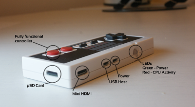 We start with [usedbytes] and Zero Entertainment System [usedbytes] has crammed an entire emulator into a classic Nintendo Entertainment System control pad thanks to the Raspberry Pi Zero. Zero Entertainment System also has something the original NES couldn’t dream of having: An HDMI output. The emulator uses the popular RetroPie front end. We’re happy to say that [usedbytes] knew that hacking up a real Nintendo controller would be sacrilegious, so they grabbed a low-cost USB clone from the far East. A bit of creative parts-stuffing and point-to-point wiring later, ZES was ready to meet the world!
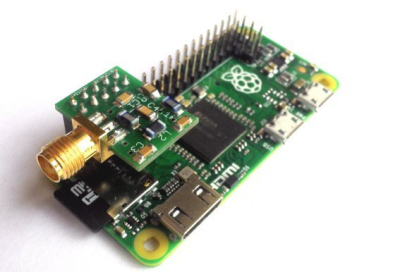 Next up is [Jenny List] with The Australia Project. [Jenny] is a hacker from Europe. She’s hoping to use a Pi Zero to talk to Australia. “Talk” may be pushing it a bit though. The Australia Project will use the Weak Signal Propagation Reporter (WSPR) network to transmit RF straight out of the Pi’s GPIO ports. All that is required is a good filter, an antenna, and a balun. The filter in this case is a 7-pole Chebyshev low-pass filter. The filter keeps the Pi’s harmonic filled square waves from messing up every band from DC to light. [Jenny] normally sells these filters as a kit, but she’s made a special version specifically for the Pi Zero.
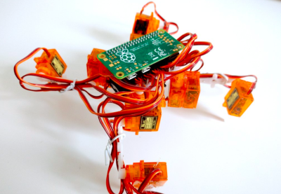 [Radomir Dopieralski] has brought his signature walking robots to the Pi Zero world with Tote Zero. Tote Zero is a quadruped walking robot built mainly from 9 gram servos. [Radomir’s] custom tote board interfaces the servos to the Pi Zero itself. The Pi Zero opens all sorts of doors for sensors, vision, and advanced processing. The Arduino board on the original Tote would have been hard pressed to pull that off. Tote is programmed in Python, which will make the code quick and easy to develop. Tote Zero just took its first steps a few days ago, so follow along as a new robot is born!
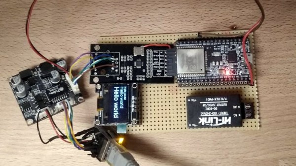
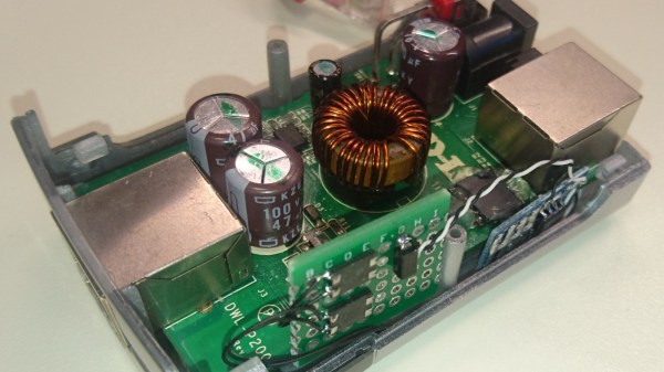
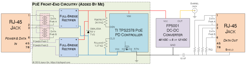
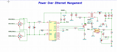 Finally we have [julien] with PoEPi: Pi Zero Power over Ethernet with PHY. The Raspberry Pi Zero is so tiny, that it’s easy to forget it needs a fair amount of power to run. [Julien] is giving us a way to connect our Pi to a network while ditching the USB power supply using Power Over Ethernet (PoE). PoE has been powering devices like IP cameras for years now. It’s become a standard way of transmitting power and data. For the Ethernet physical interface, [Julien] is using Microchip’s ENC28J60, which has a handy SPI interface. Linux already has drivers in place for the device, so it’s a slam dunk. The “power” part of this system comes with the help of an LTC4267 PoE interface chip, which has a built-in switching regulator.
If you want to see more entrants to Hackaday and Adafruit’s Pi Zero contest, check out the submissions list! If you don’t see your project on that list, you don’t even have to contact me, just submit it to the Pi Zero Contest! That’s it for this week’s Hacklet. As always, see you next week. Same hack time, same hack channel, bringing you the best of Hackaday.io!
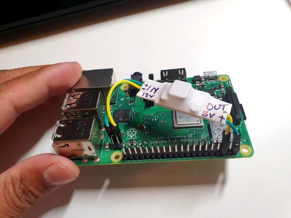
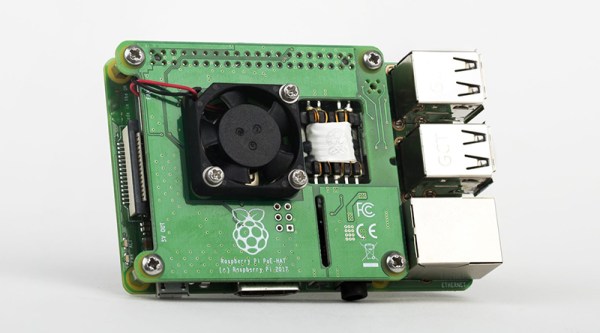
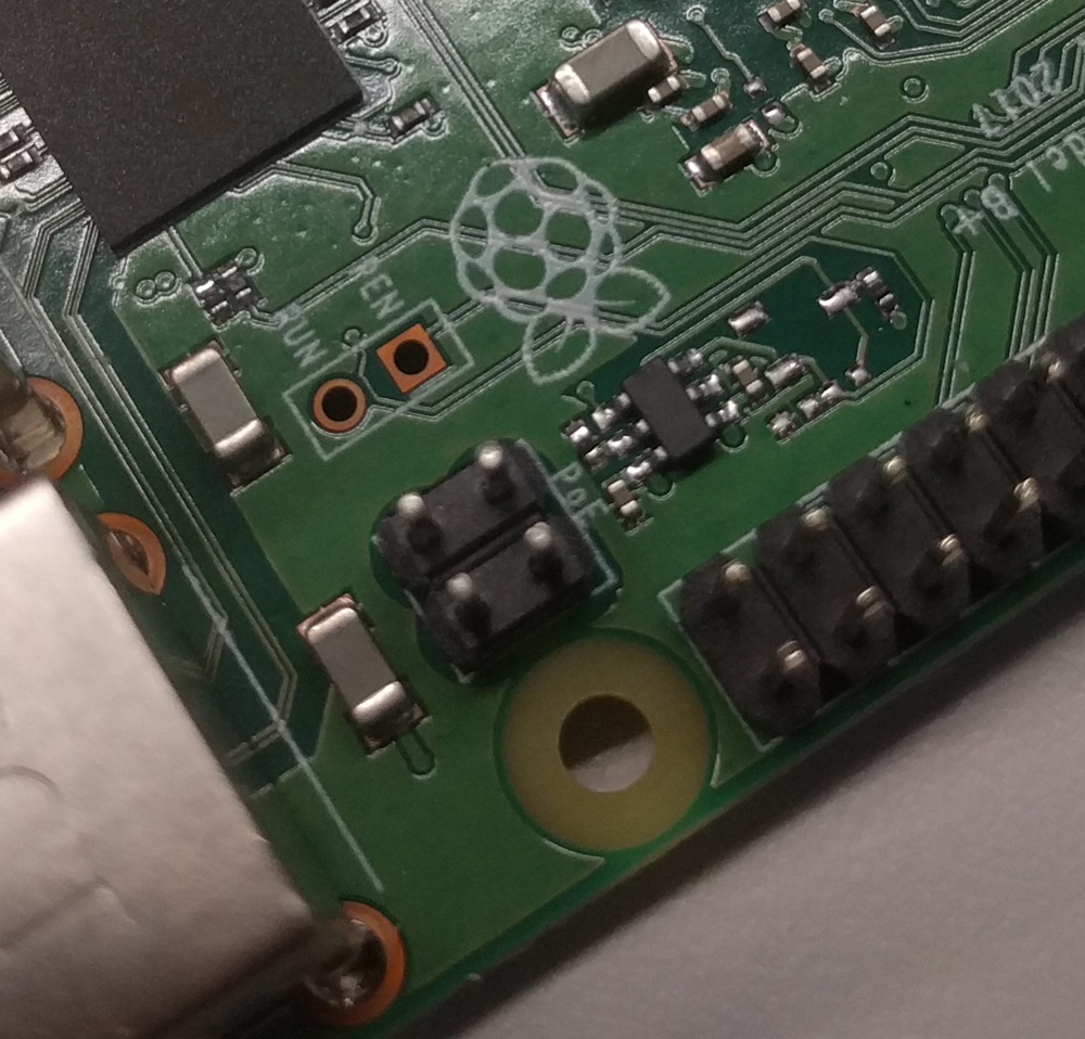
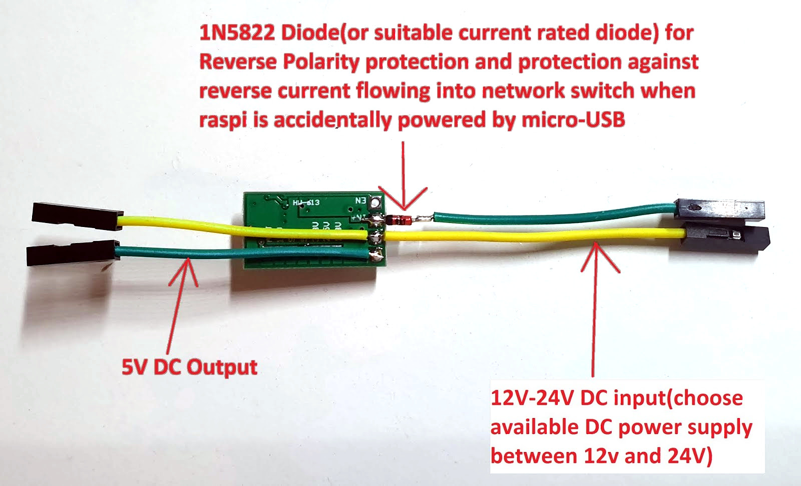 The rest of the $2 budget is mostly spent on wiring and heatshrink, resulting in a very compact PoE solution that plugs straight into the PoE header on the Raspberry Pi 3 board, with the buck converter outputs going into the ground and +5V pins on the Raspberry Pi’s GPIO header.