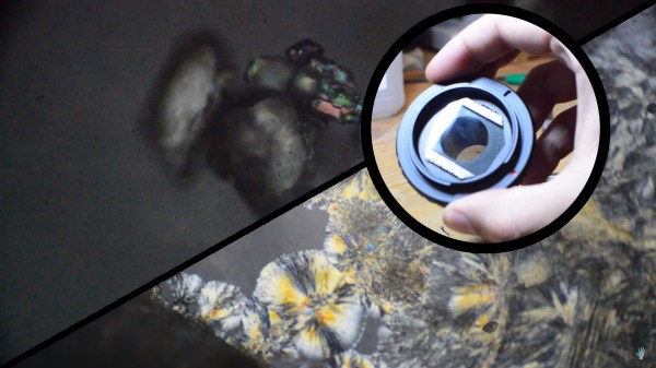
A Polar Coordinate CNC Plotter Even Descartes Could Love

Take apart a few old DVD drives, stitch them together with cable ties, add a pen and paper, and you’ve got a simple CNC plotter. They’re quick and easy projects that are fun, but they do tend to be a little on the “plug and chug” side. But a CNC plotter that uses polar coordinates? That takes a little more effort.

The vast majority of CNC projects, from simple two-axis plotters to big CNC routers, all tend to use Cartesian coordinate systems, where points on a plane are described by their distances from an origin point on two perpendicular axes. Everything is nice and square, measurements are straightforward, and the math is easy. [davidatfsg] decided to level up his CNC plotter a bit by choosing a polar coordinate system, with points described as a vector extending a certain distance from the origin at a specified angle. Most of the plotter is built from FischerTechnik parts, with a single linear axis intersecting the center point of a rotary drawing platform. Standard G-code is translated to polar coordinates by a Java applet before being sent to a custom Arduino controller to execute the moves. Check out the video below; it’s pretty mesmerizing to watch, and we can’t help but wonder how a polar 3D-printer would work out.

Have polar coordinates got you stumped? It can be a bit of an adjustment from Cartesian space for sure. It can be worth it, though, showing up in everything from cable plotters to POV fidget spinners and even to color space models.

Continue reading “A Polar Coordinate CNC Plotter Even Descartes Could Love”

Polar Coordinate Mapping And RGB LED Disks

Last week, Adafruit released the DotStar RGB LED Disk, a 240mm diameter disk packed with 255 individually addressable RGB LEDs. Because blinkey glowey projects are the best projects, [Adam] had to have one. His tests open up some interesting possibilities in the world of blinkey LED stuff, including a polar coordinate display that would be perfect for low-res games and LED clocks.

[Adam] found the Disk sufficiently bright and glowey, but there were two problems. The first was the JST SM connector on the input of the DotStar Disk; with 255 LEDs on the disk, it has a maximum draw of over 10A, while the connector can only supply 7A without getting unreasonably warm. Secondly, there aren’t 60 LEDs around the outer edge of the disk, limiting its application as a clock.

There’s another thing wrong with the DotStar Disk, until you realize it’s effectively a polar coordinate display. RGB LED libraries are usually written for strips or matrices, not circles. The LEDs are sequentially arranged on the DotStar disk spiraling inwards, and after mucking about with some terrible code, [Adam] realized he could control a pixel with only its distance from center and angle from the connector. This makes plotting circles easier, but it also opens this display up to some interesting applications; circular Pong would be cool, and LED clocks are the bees knees.

Bipolar Bot For Drawing Spirals

[Bart Dring] is well known around these parts for Makerslide, the buildlog.net laser cutter, and a collaboration with Inventables for the Carvey CNC machine. They’re all popular projects and all very useful. This one, not so much. It’s a bipolar bot that doesn’t take itself too seriously, and this year’s build for [Bart]’s usual gonzo CNC machine for ORD Camp.

The Bipolar Bot – yes, that’s its name – is pretty much a SCARA bot. There are two NEMA 14 steppers in the joint of two arms, each of which are bolted to a bearing on a base plate with the other end holding a pen. That’s it as far as the mechanics go, but the software is extremely interesting.

The steppers are driven by an Arduino with the help of a tool that converts Cartesian Gcode to the bipolar Gcode the machine requires. There’s a bit of math involved, but nothing of note if you can code some trig functions

Right now the bipolar bot is busy drawing stuff that looks like it came right off a spirograph. You can see a video of that below.

Continue reading “Bipolar Bot For Drawing Spirals”

Center Pivot Pen Plotter

This center pivot pen plotter is an interesting take on the idea, and manages to somewhat simplify the fabrication when compared to a gantry-style built.

Normally we’d see a gantry that travels on two rails, with a print head that moves along its length. Here the gantry is anchored on just one side, with a chain driven system to rotate it along the plotting surface. The print head uses a fine-point felt-tipped marker. It still travels along the arm as you would expect, and can be tilted away from the paper for repositioning.

What was made easier in hardware ends up adding to software complexity. The benefit of a traditional system is that it uses X and Y coordinates to plot a design. The pivot of this mechanism means that as the print head moves further from the center of the machine, the distance between each pixel is magnified. But the clip after the break proves that this issue has been solved.

Continue reading “Center Pivot Pen Plotter”

Pushing Chest Strap Heart Rate To A Stock Exerciser Display

This hack came out so well that [Levent] wishes he had tried it years ago. When exercising he wears a Polar heart rate monitor which sends data from a chest strap to his wristwatch. But his exercise bike also has a heart rate readout that depends on your hands touching metal contacts on the handlebars. He set out to see if he could patch the chest strap data into the exercise bike LCD display.

The first part of the hack is really simple. As we’ve seen several times before, you can buy a receiver module which grabs data from the chest strap. Now it was a matter of patching the data from this receiver into the Schwinn 213 recumbent exercise bike. [Levent] pulled out the PCB and located the small daughterboard that is responsible for the hand grip heart rate. With careful study he was able to identify the pinout. There are two data lines. One is responsible for the heart rate detected signal, the other pushes the actual heart rate data. On a hunch he hooked a signal generator up to the latter and discovered that all it takes is a square wave.

The rest is pretty straight forward. Check out the proof in his video after the break. Continue reading “Pushing Chest Strap Heart Rate To A Stock Exerciser Display”

Arduino Heart Rate Monitor

[Wolf] had a Polar brand exercise watch that wirelessly monitored a chest strap that sends it heart rate data. It sounds like there’s some way to transfer data from the watch to a computer, but it’s only meant for use with Polar’s website. He wanted to do a little more with the equipment so he ditched the watch and built an Arduino-based heart rate monitor.

He’s still using the chest strap and was happy to find that SparkFun sells an OEM receiver for it. Just add a 32.768 kHz clock crystal and an optional antenna wire and you’re up and running. Once the receiver finds a transmitting chest strap, it will pulse an output pin with each beat of the heart. [Wolf] used the D2 pin of an Arduino Uno to connect to the receiver because this pin corresponds to one of the ATmega’s external interrupts. A rolling average of five inputs are used to help smooth the display data, which is shown on the 2.8″ LCD screen seen above.