Giant Spinning POV Christmas Tree

Spinning Holographic POV Christmas Tree Of Death

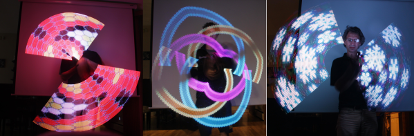
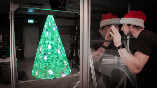
[Sean Hodgins] really harnessed the holiday spirit to create his very own Giant Spinning Holographic Christmas Tree (of Death). It’s a three-dimensional persistence-of-vision (POV) masterpiece, but as a collection of rapidly spinning metal elements, it’s potentially quite dangerous as well. As [Sean] demonstrates, the system can display other images and animations well beyond the realm of mere holiday trees.

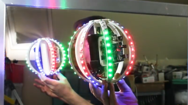
Initial experiments focused on refining the mechanical structure, bearings, and motor. A 1/2 horsepower A.C. motor was selected and then the dimensions of the tree were “trimmed” to optimize a triangular frame that could be rotated at the necessary POV speed by the beefy motor.  A six-wire electrical slip ring allows power and control signaling to be coupled to the tree through its spinning central shaft.

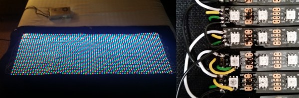
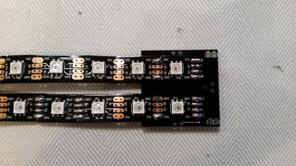
The RGB elements are SK9888 LEDs also know as DotStar LEDs. DotStar LEDs are series-chainable, individually-addressable RGB LEDs similar to NeoPixels. However, with around 50 times the pulse width modulation (PWM) rate, DotStars are more suitable for POV applications than NeoPixels.  The LED chain is driven by a Raspberry Pi 4 single board computer using a clever system for storing image frames.

If deadly rotational velocity is not your cup of tea, consider this slower spinning RGB Christmas tree featuring a DIY slip ring. Or for more POV, may we suggest this minimalist persistence-of-vision display requiring only a few LEDs and an ATtiny CPU.

Continue reading “Spinning Holographic POV Christmas Tree Of Death”

POV LED Staff Takes Art For A Spin

The human body does plenty of cool tricks, but one of the easiest to take advantage of is persistence of vision (POV). Our eyes continue to see light for a fraction of a second after the light goes off, and we can leverage this into fun blinkenlight toys like POV staffs. Sure, you can buy POV staffs and other devices, but they’re pretty expensive and you won’t learn anything that way. Building something yourself is often the more expensive route, but that’s not the case with [shurik179]’s excellent open-source POV staff.

There’s a lot to like about this project, starting with the detailed instructions. It’s based on the ItsyBitsyM4 Express and Adafruit’s Dotstar LED strips. You could use the Bluetooth version, but it’s already quite easy to load images to the staff because it shows up as a USB mass storage device. We like that [shurik179] added an IMU and coded the staff so that the images look consistent no matter how fast the staff is spinning. In the future, [shurik179] might make a Bluetooth version that’s collapsible. That sounds like quite the feat, and we can’t wait to see it in action.

As cool as it is to wave a POV staff around, there’s no real practical application. What’s more practical than a clock?

Gyro Controlled RGB Blinky Ball Will Light Up Your Life

[James Bruton], from the XRobots YouTube channel is known for his multipart robot and cosplay builds. Occasionally, though, he creates a one-off build. Recently, he created a video showing how to build a LED ball that changes color depending on its movement.

The project is built around a series of 3D printed “arms” around a hollow core, each loaded with a strip of APA102 RGB LEDs. An Arduino Mega reads orientation data from an MPU6050 and changes the color of the LEDs based on that input. Two buttons attached to the Mega modify the way that the LEDs change color. The Mega, MPU6050, battery and power circuitry are mounted in the middle of the ball. The DotStar strips are stuck to the outside of the curved arms and the wiring goes from one end of the DotStar strip, up through the middle column of the ball to the top of the next arm. This means more complicated wiring but allows for easier programming of the LEDs.

Unlike [James’] other projects, this one is a quickie, but it works as a great introduction to programming DotStar LEDs with an Arduino, as well as using an accelerometer and gyro chip. The code and the CAD is up on Github if you want to create your own. [James] has had a few of his projects on the site before; check out his Open Dog project, but there’s also another blinky ball project as well.

Continue reading “Gyro Controlled RGB Blinky Ball Will Light Up Your Life”

Have Your Own 200 Water Street Digital Clock

On the front of a building in New York City, above a branch of the ubiquitous Starbucks coffee chain, there is a clock. It is no ordinary clock, the 200 Water Street clock is an art installation created by the artist [Rudolph de Harak], and consists of 72 lighted numbers which are illuminated in sequence to show hours, minutes, and seconds. It is a landmark of sufficient fame that [Jason Ben Nathan] and [Eldar Slobodyan], Cornell University students of [Bruce Land], decided to make their own tribute to it as their course project.

Water Street clock at night
Water Street clock at night [via NYC ♥ NYC]
It’s a fairly straightforward build, thanks to the use of Adafruit Dotstar multicolour LED strips which are populated with APA102 pixels. Behind the scenes is a PIC32 microcontroller, and the time information comes from an off-the-shelf 60kHz WWVB time signal receiver. There is also a temperature sensor, for a handy second function.

The front panel is a piece of ply with the required numbers nicely laser-cut. All the schematics and code are available, should you fancy your hand at building your own version of the clock.

If you are curious about the real-life clock here’s an image. But you get a much more interesting perspective if you stand in front of it. If you just can’t go there, get an approximation through the wonders of Google Street View.

Look Out DotStar, Here Comes Lumenati

Adafruit has long been the undisputed ruler of the smart LED product, with their WS2812B (NeoPixel) and APA102C (DotStar) product lines dominating due to the robust assortment of sizes and form factors, as well as their ease of use. SparkFun Electronics recently announced Lumenati, their new line of APA102C breakouts that feature some intriguing features which do a good job of distinguishing the two lines.

First, the screen-printing on the boards include pixel numbers. We were working on NeoPixel assemblies the other day and keeping track of pixels was a nightmare. In addition, the Lumenati boards are meant to combine into larger creations, allowing you to make complicated shapes. SparkFun supports this by giving the boards castellated headers — far better than the solder pads! If you are running into logic conflicts with the boards you can solder in jumpers to bypass the data connections and control individual boards separately. On the down side, SparkFun’s intitial offerings — 6 products — still can’t compete with Adafruit’s, like their 255-LED disk, shields, strips, matrices, and flexible PCBs.

We’ve published a few DotStar builds over the years, like this violin bow lightsaber and the Magicshifter POV stick. Maybe we’ll start seeing some Lumenati builds? Continue reading “Look Out DotStar, Here Comes Lumenati”

Who Needs The MSP430 When You Have TI’s Other Microcontroller, The TI-84?

We’re sure there are more expensive LED controllers out there, but the TI-84 has got to be up there. Unless you have one on hand, then it’s free. And then you’ll doubtless need an SPI library for the famously moddable graphing calculator.

[Ivoah] is using his library, written in assembly for the Z80 processor inside the TI, to control a small strip of DotStar LEDs from Adafruit. The top board in the photograph is an ESP8266 board that just happened to be on the breadboard. The lower Arduino is being used as a 5V power supply, relegated to such duties in the face of such a superior computing device.

Many of us entertained ourselves through boring classes by exploring the features of TI BASIC, but this is certainly a step above. You can see his code here on his GitHub.

After his proof-of-concept, [Ivoah] also made a video of it working and began to program a graphical interface for controlling the LEDs. Video after the break.

Continue reading “Who Needs The MSP430 When You Have TI’s Other Microcontroller, The TI-84?”

LED Matrix Failure And Vindication

If necessity is the mother of invention, what’s failure the mother of? Improvement? Anyway, [prpplague]’s second version of his roll-up 70×30 RGB LED display looks a lot better and more reliable than the first, and that’s precisely due to “failing”.

Sometimes you design the hardware around the software, and sometimes vice-versa. It’s all about the balance of pain. [prpplague] initially wired the strips together in a consistently left-to-right raster arrangement to make the coding easier, but this means long wires on the backside of the fabric returning from the right side back to the start again at the left. These long wires snagged on stuff, and pulled the solder connections apart.

600px-Dotstar-adapter-solder3The fix? Alternate rows of left-to-right with right-to-left to minimize wiring and make nice, robust connectors for the ends, and a much more elegant implementation at the expense of more complicated software to drive the device. (Alternating rows have to be flipped horizontally, so this means custom driver routines.)

The second gremlin was that the interfacing board that [prpplague] was using didn’t have enough current sourcing capability on the SPI lines, and he discovered that he couldn’t communicate reliably with the strings if the first pixel was more than 24″ of wire away from the board. Once the signal got to the first pixel, though, everything was fine. [prpplague] figured out that the RGB LEDs themselves had more drive capability than the SPI source.

The solution? Add a single pixel at the front of the chain to buffer the SPI lines and serve as a bonus status indicator. Cute.

We’d hardly call these “fails”, but rather “learning experiences”. Anyway, here’s two design “mistakes” that we won’t make when making a roll-up flexible pixel display. Thanks [prpplague].