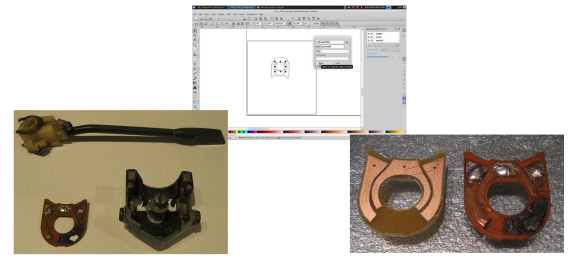
[John] has managed to replace a broken turn signal PCB by scanning it and converting to Gerber format. [John] purchased a Triumph Spitfire with toggle switch wired up for turn signal control. The “official” replacement part worked better than the toggle switch, but it didn’t cancel after turning. He was able to get the original switch, only to find it had a hole completely burned through the phenolic board. This isn’t completely surprising, as Triumph used a Lucas Industries electrical system. As anyone who has owned a car with a Lucas “prince of darkness” electrical system will tell you, Lucas systems were not known for quality. A quick Google search brings up plenty of pages attesting to this.
Phenolic resin/paper was a common early PCB material. The FR-4 fiberglass boards most commonly used today could be considered descendants of FR-1 and FR-2 phenolic. (The FR in this case stands for Fiber Reinforced). The standardization worked in [John’s] favor, as his burned board was 31 mils thick, which is still a standard PCB thickness. Re-creating an odd sized board such as this isn’t a hard job. It would however mean spending quite a bit of time with a ruler and a caliper. Rather than spend all that time measuring and re-drawing, [John] scanned his PCB on a flatbed scanner. He used graph paper as a background to verify the image wasn’t being stretched or skewed.
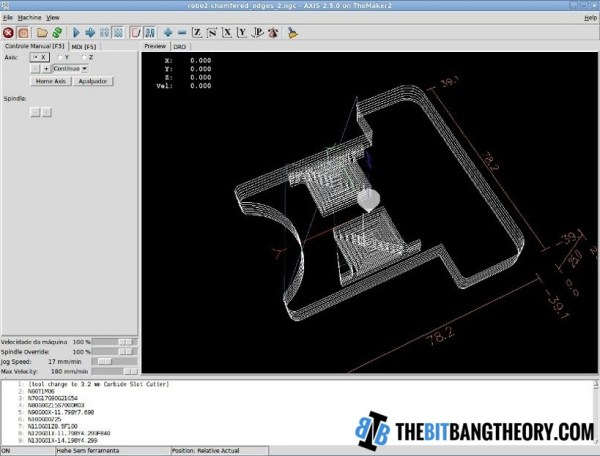
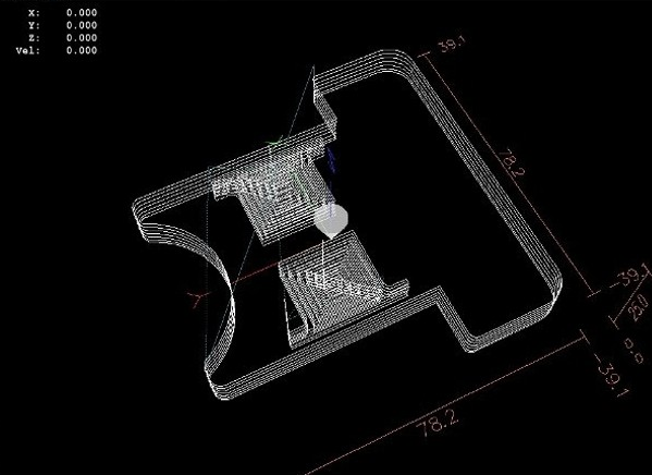
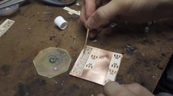
[John] brought his scan into inkscape, and traced both the outline and copper areas. The outline and copper had to be exported as two separate files, so he added corner marks outside the board outline as fiducials. He then used pstoedit to convert inkscape’s eps output files to gEDA pcb format. The two files were rejoined in gEDA. From there [John] exported a Gerber, and ran it on his home PCB milling machine. The results look good. [John] plans to make another revision of the board from a professional PCB house with vias to hold the copper to the substrate.