Organize That Messy Prototype

You’re working away busily at your project. A pcb here cabled to a breadboard in the middle, and over there some motors and other devices. It should work but it doesn’t. Time to hook-up the multimeter but the test point is on the other side. As things are moved around to reach the point, the magic smoke escapes from a critical component. Should have put those pliers away.

Workbenches are always messy. [Ryan Clark] may have an idea that can help.  His Jigmod system — currently running a kickstarter campaign — uses an acrylic a polycarbonate sheet with a grid of mounting holes to keep prototyping hardware in place. If you need to move the prototype around there is no strain on the wiring and no way to set a circuit down on that pair of pliers. The positioning of everything is your decision.

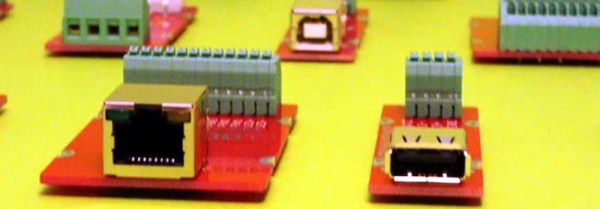
[Ryan] is also providing breakout type boards for connectors like USB and Ethernet, switches, battery holders, and other typical components. This is one place where the system really shines. A lot of these interface connectors tend to be breadboard-unfriendly and the terminal blocks these modules offer solves those issues. When you need to demonstrate your project it’s easy to transport since everything is attached to the plate. No more disconnecting cables, especially jumper wires, and hoping you get them all hooked back the right way at the destination.

With so many dev boards out there we really enjoy seeing jigs that can hold them along with a breadboard. This Stickvise-inspired 3D printed jig sticks out in our minds as a favorite. Do you have your own system of organizing your prototype builds? We’d love to hear about it in the comments!

Hackaday Video: Wire Wrap 101 with Bil Herd

Wire Wrap 101

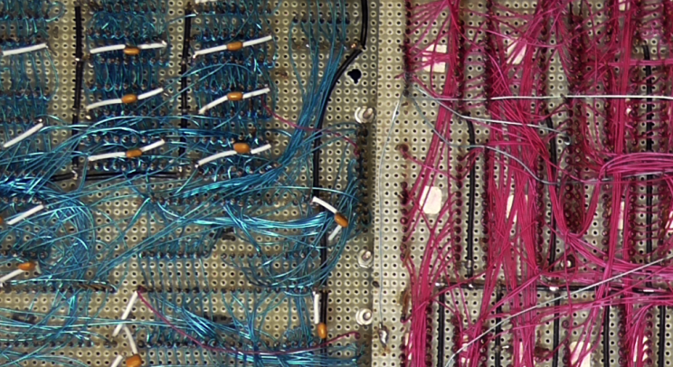
You might notice that many of my writings start with “Back in the day”. Not wanting to disappoint I will say that back in the day we used to use wire wrap technology when we needed a somewhat solid, somewhat reliably assembly. Given a readable schematic a good tech could return a working or near-working unit in a day or two depending on the completeness and accuracy of the schematic.

wire-wrap2

Properly done a wire wrap assembly is capable of fairly high speed and acceptable noise when the alternative option of creating a custom PCB would take too long or not allow enough experimentation.  Wire wrap is also used in several types of production, from telco to NASA, but I am all about the engineer’s point of view on this.

My first wire wrap tool and wire wrap wire came from Radio Shack in the mid 1970’s.  I still have the wire, because frankly its kind of cheap wire and I use it when it’s the only thing I can reach quickly when I need to make a jumper on a PCB. The tool is still around also, given the fact that I can’t find it at the moment the one shown here is my new wire wrap tool which is good for low quantity wrapping, unwrapping and stripping.

ww-tool2The skinny little wrap tool is okay for hobbyist as the wraps are fine with a little practice.  But I do recommend investing in high-quality wire.  A common wire available is Kynar® coated, a fluorinated vinyl that performs well as an insulator.

Before I go too much further, here’s the video walkthrough of wire wrap, its uses, and several demonstration. But make sure you also join me after the break where I cover the rest of the information you need to start on the road to wire wrap master.

Continue reading “Wire Wrap 101”

From Schematic To PCB In Four Hours

lpkf_metrix

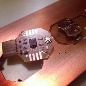
Last super bowl Sunday, instead of checking the game, [Mattw] decided to extend a design and make a PCB of a trinket clone. [Mattw] altered a trinket clone design by [Morgan Penfield Redfield] to shrink it down, perforated the USB connector to allow for easy removal and put most of the parts on a single layer.

After finalizing the design, [Mattw] put it into the LPKF Protolaser S that Seattle’s Metrix Create Space has. For those of you who don’t know, the LPKF protolaser uses a laser to directly ablate off the copper from the boards.  This makes prototyping much faster without the need for a lot of nasty chemicals.

About six minutes in the Protolaser, some component placement by hand followed by a run through their reflow oven and [Mattw] had three boards ready to be tested. All told, about 4 hours from start to finish.

The end circuit looks great and the LPKF protolaser gives us a case of serious tool envy. If you’re like us and don’t have access to the fancy laser you might try our hand at this high-resolutino photo-etch process.

[via reddit]

Propeller Platform

Propellor_Platform

[nmcclana] has posted an assembly walkthrough for an Arduino-style prototyping board for the 80 MHz, eight core Parallax Propeller Microcontroller. While not board compatible with Arduino shields like the ARM-based Maple board we covered, it does have that familiar layout, and provides access to all 32 I/O pins, and the 3.8″ x 2.5″ footprint was kept in mind to allow easy creation of shields modules that can be designed using ExpressPCB’s miniboard service. The Platform Kit also has the advantage over other Propeller kits such as SchmartBoard’s offerings, which require soldering of surface mount parts. Kits are available at Gadget Gangster, and ready for your next design that needs a little more sauce than the Arduino can offer.