While most embedded development is still done in C and/or assembly, some people are working with more modern languages. The team over at Gobot has successfully managed to get Go running on the Intel Edison.
The Go programming language, which has been around for about five years, compiles to machine code like C. It has a number of modern features including concurrency, garbage collection, and packages.
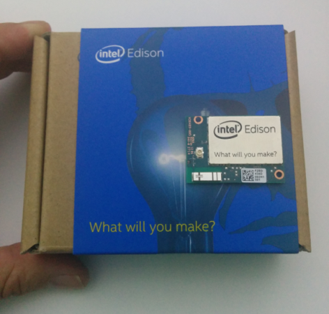
We’ve looked at the Edison on Hackaday before, and even took a detailed look at the hardware. It features a Quark SoC, Bluetooth, and WiFi, which makes it well suited for connected devices.
Getting Go to work on the Edison hardware wasn’t particularly difficult, since it supports the Pentium instruction set and MMX. However, a library was needed to interface with the Edison’s peripherals. The Gobot team whipped up gobot-intel-iot, which makes it easy to work with GPIO, I2C, and PWM.
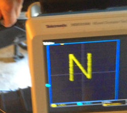
After the break, the team demos PWM on the Edison using Go.
Continue reading “Running Golang On The Intel Edison”
 The project featured in this post is
 A few years ago, [Pat] sent in
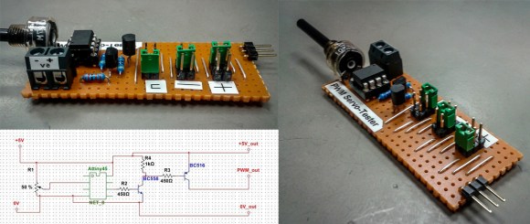
 When you think of a robotic arm, you’re probably thinking about digital control, microcontrollers, motor drivers, and possibly a feedback loop. Anyone who was lucky enough to have an Armatron knows this isn’t the case, but you’d still be surprised


