Amateur radio is a hobby that is often thought of as being exclusive to those with a healthy expendable income. In recent years however, the tides have turned. Cheap microcontrollers and signal generators have helped turned things around, and the $60 USD QDX from QRP Labs goes even further by sending the performance/price ratio through the roof. You can see more details in the video below the break.
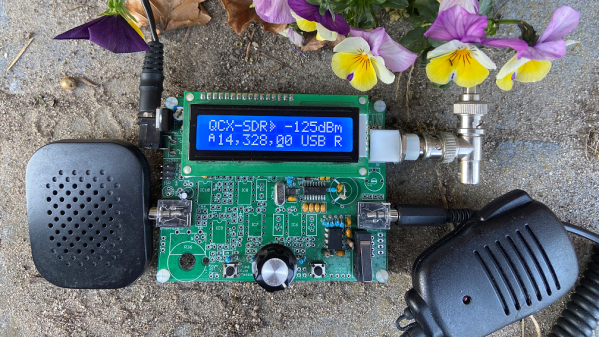
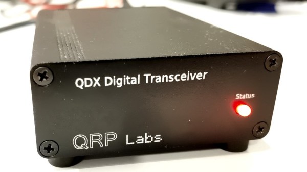
The QDX is the creation of [Hans Summers] who is well known for producing affordable high performance amateur radio kits that are focused on low power transmission, called “QRP” in ham radio parlance. What is it? It’s a pocket sized four band (80, 40, 30, 20 Meters) software defined radio (SDR) that is designed to be used with some of the most popular digital radio modes: FT8 and JS8Call, as well as any other FSK based mode such as RTTY. It’s also been tested to work well (and within spec) on 60 Meters.
While classic radios have to be connected to a computer through a special hardware interface, the QDX is designed to connect directly to a computer through a standard USB A>B cable. CAT control, PTT, and Audio are all handled directly by the QDX, and no special interface is needed. While the radio is essentially plug and play, configuration, testing, and troubleshooting can be done by connecting to the QDX’s unique serial console, which among other things contains a text based waterfall. For those who want to run their own SDR receiver, I/Q output can be sent directly through the sound card.
Now for the bad news: due to global chip shortages, the QDX is out of stock at the moment, and there’s no telling when they might start shipping again. QRP Labs is looking to source parts wherever they can to get more of the units made, but of course, so is everyone else right now. Continue reading “Four Band Digital HF SDR Transceiver Offers High Performance For Only $60”