Hackaday Prize Entry: Sub Gigahertz RF

For all the press WiFi and Bluetooth-connected Internet of Things toasters get, there’s still a lot of fun to be had below one Gigahertz. For his Hackaday Prize entry, [Adam] is working on an open source, extensible 915 and 433 MHz radio designed for robotics, drones, weather balloons, and all the other fun projects that sub-Gigaherts radio enables.

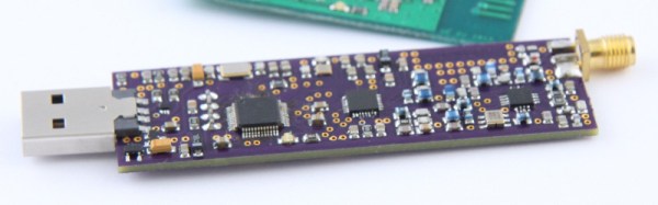
The design of this radio module is based around the ADF7023 RF transceiver, a very capable and very cheap chip that transmits in the usual ISM bands. The rest of the circuit is an STM32 ARM Cortex M0+, with USB, UART, and SPI connectivity, with support for a battery for those mobile projects.

Of course, you can just go out and buy an ISM radio, but that’s not really the point of this project. [Adam] has come up with an excellent board here, all designed in KiCad, all while flexing his RF muscle. There are RF shields here, too, so it’s far more than just a design challenge, this is an assembly and sourcing problem as well. It’s a great project, and an excellent example of what we’re looking for in The Hackaday Prize.

A Tube AM Transmitter In A Soup Can

A standard early electronics project or kit has for many years been the construction of a small broadcast transmitter with enough power to reach the immediate area, but no further. These days that will almost certainly mean an FM broadcast band transmitter, but in earlier decades it might also have been for the AM broadcast band instead.

The construction of a small AM transmitter presents some interesting problems for an electronic designer. It is extremely easy to make an AM transmitter with a single transistor or tube, but it is rather more difficult to make a good one. The modulation has to be linear across the whole amplitude range, and its effect must not pull the frequency of the oscillator and cause FM distortion.

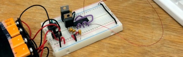
It’s a task [Joe Sousa] has tackled, with his one tube AM transmitter in a Campbell’s soup can. His write-up of the transmitter contains a full description of the problems he faced, and how his design overcomes them. His oscillator is a cathode follower, with the tube biased in class A mode to ensure as undistorted a sine wave oscillation as possible. Modulation is provided through the suppressor grid of the pentode tube he’s using.

The completed transmitter is mounted inside the iconic soup can, with the mains transformer mounted on a removable bottom plate. There is a provision for both loop and wire antennas to be connected.

It is probable that this transmitter falls under the so-called “Part 15” rules for unlicenced low-power broadcasting in the USA, however it should be borne in mind that not every territory has this provision. If you build this transmitter, make sure you’re not going to attract the interest of your local equivalent of the FCC.

This article should have whetted your appetite for tiny broadcast transmitters. How about comparing the one here with a full-sized model?

Thanks [2ftg] for the tip.

A Remotely Tuned Magnetic Loop Antenna

If you are a radio amateur, you may be familiar with the magnetic loop antenna. It’s different from most conventional wire antennas, taking the form of a tuned circuit with a very large single-turn coil and a tuning capacitor. Magnetic loops have the advantage of extreme selectivity and good directionality, but the danger of a high voltage induced across that tuning capacitor and the annoyance of needing to retune every time there is a frequency change.

[Oleg Borisov, RL5D] has a magnetic loop, and soon tired of the constant retuning. His solution is an elegant one, he’s made a remote retuning setup using a stepper motor, an Arduino, and a Bluetooth module (translated here). The stepper is connected to the capacitor via a short flexible coupling, and tuning is performed with the help of a custom Android app. We’d be interested to know what the effect of a high RF field is on these components, but he doesn’t report any problems so it must be working.

He’s posted a video of the unit in operation which we’ve posted below the break, if you’ve ever had to constantly retune a magnetic loop you will appreciate the convenience.

Continue reading “A Remotely Tuned Magnetic Loop Antenna”

Phase Modulation With An FPGA

There are two radio modulation schemes everyone should know. Amplitude modulation changes the amplitude — or ‘volume’, if you will — of a carrier frequency and turns all radio into channels owned and operated by a church. Frequency modulation changes the pitch of a carrier frequency and is completely run by Clear Channel. Amateur radio operators are familiar with dozens of other modulation schemes, but there’s one hardly anyone touches. Phase modulation is weird and almost unheard of, but that doesn’t mean you can’t implement it on an FPGA. [nckm] is transmitting audio using phase modulation on an FPGA (Russian, here’s the Google Translatrix).

This hardware is just an Altera MAX10 board, with a single input used for serial data of the audio to be transmitted, and two outputs, each connected to a few bits of wire for a quarter-wave antenna. No, there’s no output filter or anything else except for a few bits of wire. It’s an experiment, chillax.

The Verilog for this project receives an audio signal as serial data in mono, 22050 BPS, 8-bit unsigned samples. These samples are fed into a dynamic PLL with phase shift in the FPGA. Shifting the phases also changes the frequency, so [nckm] can receive this audio signal with the FM transmitter on his phone.

Is this really phase modulation if it’s being received by an FM radio? Eh, maybe. PM and FM are closely related, but certainly distinguishable as modulation schemes in their own right. You can grab [nckm]’s code over on the gits, or check out the video demo below.

Continue reading “Phase Modulation With An FPGA”

Simple Range Testing For LoRa Modules

WiFi and Bluetooth have their use cases, but both have certain demands on things like battery life and authentication that make them unsuitable for a lot of low-power use cases. They’re also quite limited in range. There are other standards out there more suitable for low-power and wide area work, and thankfully, LoRa is one of them. Having created some LoRa pagers, [Moser] decided to head out and test their range.

Now, we’ve done range tests before. Often this involves sending one party out with a radio while the other hangs back at base. Cellphones serve as a communications link while the two parties go back and forth, endlessly asking “Is it working now? Hang on, I’ll take a few steps back — what about now?”

It’s a painful way to do a range test. [Moser]’s method is much simpler; set a cellphone to log GPS position, and have the pager attempt to send the same data back to the base station. Then, go out for a drive, and compare the two traces. This method doesn’t just report straight range, either — it can be used to find good and bad spots for radio reception. It’s great when you live in an area full of radio obstructions where simple distance isn’t the only thing affecting your link.

Build details on the pagers are available, and you can learn more about LoRa here. While you’re at it, check out the LoRa tag for more cool builds and hacks.

Pi Network Attenuators: Impedance Matching For The Strong Of Signal

If you catch a grizzled old radio amateur propping up the bar in the small hours, you will probably receive the gravelly-voiced Wisdom of the Ancients on impedance matching, antenna tuners, and LC networks. Impedance at RF, you will learn, is a Dark Art, for which you need a lifetime of experience to master. And presumably a taste for bourbon and branch water, to preserve the noir aesthetic.

It’s not strictly true, of course, but it is the case that impedance matching at RF with an LC network can be something of a pain. You will calculate and simulate, but you will always find a host of other environmental factors getting in the way when it comes down to achieving a match. Much tweaking of values ensues, and probably a bit of estimating just how bad a particular voltage standing wave ratio (VSWR) can be for your circuit.

Continue reading “Pi Network Attenuators: Impedance Matching For The Strong Of Signal”

RadiantBee Is A Flying Microwave Antenna Calibration System

Many of the projects we link to here at Hackaday have extensive write-ups, pages of all the detail you could need. Sometimes though we happen upon a project with only a terse description to go on, but whose tech makes it one worth stopping for and unpicking the web of information around it.

Such a project is [F4GKR] and [F5OEO]’s RadiantBee, an attempt to use a beacon transmitter on a multirotor as an antenna calibration platform. (For more pictures, see this Twitter feed.) In this case a multirotor has a GPS and a 10 GHz beacon that emits 250 ms chirps, from which the receiver can calculate signal-to-noise ratio as well as mapping the spatial response of the antenna.

The transmitter uses a Raspberry Pi feeding a HackRF SDR and a 10 GHz upconverter, while the receiver uses an RTL-SDR fed by a 10 GHz to 144 MHz downconverter. The antennas they are testing are straightforward waveguide horns, but the same principles could be applied to almost any antenna.

There was a time when antenna design at the radio amateur level necessitated extensive field testing, physical measurements with a field strength meter over a wide area, correlation of figures and calculation of performance. But with computer simulation the field has become one much more set in the lab, so it’s rather refreshing to see someone producing a real-world simulation rig. If you ever get the chance to evaluate an antenna through real-world measurement, grasp it with both hands. You’ll learn a lot.

We’ve covered very few real-world antenna tests, but there is mention in this write-up of a radar antenna test of a measurement session on a football field.

Via Southgate ARC.