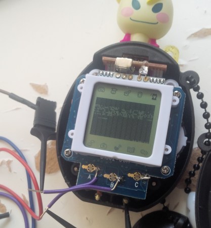
Reverse Engineering A Stylophone

The Stylophone – a musical toy from the 60s – is a surprisingly simple piece of engineering. With a simple metallic keyboard played with a stylus and just a handful of transistors, the Stylophone was able to produce a few marvelous for their time sounds, and is the equivalent of a pre-[Stradivarius] violin for the electronic music scene. [Simon] tore apart an original Stylophone, and did a complete teardown of the circuit, going over the ins and outs of why this ancient noise box is so cool.

There have been quite a few DIY Stylophone clones, but all of them suffered from the same raspy sound made by a 555 timer chip slightly misguided makers used instead of the relaxation oscillator (in the pic seen above) used in the original. Aside from the oscillator connect to the RC circuit of the metallic keyboard, [Simon] also looked into the vibrato circuit. This is just a simple oscillator producing an 8 Hz sine-ish wave. The keyboard, of course, is connected to the circuit with an array of resistors which [Simon] happily provided the values for.

[Simon] put up a schematic of his reverse engineered Stylophone, allowing you to clone this ancient electronic instrument. If you can source the transistors, that is.

Re-engineering Some FM Transmitter Firmware

[Furrteck] had a little adventure with this FM transmitter he picked up on eBay. It worked alright, but he wanted to be able to scan through the frequencies, and to have the device return to the same settings after power cycling. He cracked it open and got to work to achieve all of his goals.

The device is driven by an ATmega48, and there’s a 6-pin ISP header on the board. An initial read of the chip wouldn’t work, and he soon discovered the unstable power supply was to blame. After connecting his own regulated source he could read the chip id without a hitch, but the code is locked so no dumping was possible. Fortunately he managed to trace out the board, and includes a full schematic in his write up. With this in hand he erased the chip and started programming his own firmware from the ground up.

The video after the break shows off the completed project. He can now scan through frequencies with audio feedback to let he know when he’s found a station to hijack. The new code will also write a tuned station to EEPROM for use the next time the rig is powered up.

Continue reading “Re-engineering Some FM Transmitter Firmware”

Reverse Engineering Silicon

[John McMaster] is doing some pretty amazing work with figuring out how the circuitry in an integrated circuit works. Right now he’s reverse engineering a serial EEPROM chip one section at a time. This is a 24c02 made by ST, and  he chose this particular portion of the die to examine because it looked like there were some analog components involved.

He removed the top metal using hydrofluoric acid in order to take this image. By continually removing layers this way he manages to work out the traces and even the components themselves. To help clarify the parts he uses the set of snapshots to generate a colored map using Inkscape. From there he begins labeling what he thinks the components might be, and like a puzzle the pieces start falling into place one by one. From the Inkscape drawing he lays out a schematic, then rearranges the components to make the design easier to understand. Apparently this is a Schmidt trigger.

[Thanks George]

Salvaged LCD Screen Hacking

You can find all kinds of LCD screens in broken electronics. But it’s often a chore to figure out how they are controlled if you don’t have a working device that can be used to sniff the communications protocol. [Justin] grabbed this character LCD screen from an old Brother printer and decided to see if he could reuse it in his own projects. Luckily the driver card still worked so he patched into the LCD’s control lines and sniffed the signals when the printer is powered on.

He used the OpenBench Logic Sniffer for this project. It easily captured the data, and also provided analysis tools. The SPI analyzer managed to decode the command signals and message of “Please wait” that pops up at power up. After a bit of folly with the pin out of the display, he is now able to control it thanks to an Arduino library which he wrote. Check out the demo after the break to seem him scrolling through a bunch of different functions for the device.

Continue reading “Salvaged LCD Screen Hacking”

oscope-reverse-engineering

Reverse Engineering An Oscilloscope Circumvents Vendor Crippleware

The crew over at the Hungarian Autonomous Center for Knowledge (H.A.C.K.) say they aren’t the most well-funded organization out there, so they were stoked when they found they could afford to bring a slightly used UNI-T UT2025B digital oscilloscope into the shop. As they started to tinker with it, the scope revealed one major shortcoming – screenshots were only accessible via a USB connection to a Windows computer.

Since they didn’t have any Windows boxes in house, [András Veres-Szentkirályi] decided he would try reverse-engineering the protocol so they could get access to this useful feature.

He set up a Windows VM, and using Wireshark on the host Linux box, [András] sniffed the data passing over the scope’s USB interface. He was able to identify what looked like image packets being sent to the VM, which he was able to decode using a small Python script. The resultant images were monochrome and they didn’t look quite right, but it was a start. As he dug further [András] found that he was overlooking some of the color data packed into the images, and after a bit of fiddling he got the sharp, colorful image you see above.

It turns out that while the scope has a monochrome LCD, it sends 16-bit color images over the USB interface – images that the Windows’ client degrades before displaying them on the screen. So in the end, he was not only able to get the scope working on any OS with the ability to run Python, he was able to grab far better images than the manufacturer ever intended – A very nice hack if we do say so.

Be sure to swing by the H.A.C.K. wiki as well as the project’s github repository if you have one of these scopes and are looking to wring some better images out of the hardware.

Repair A Misbehaving Motor Controller Board

It can be a real drag to fix a circuit board which has stopped working as intended, especially if you don’t have any reference material for the product. That’s the position that [Todd Harrison] found himself in when the controller for his mini-lathe gave up the ghost. He undertook and hefty repair process and eventually mapped out and repaired the driver board.

First off, we’re happy to report his success at the end of a year-long troubleshooting process; the entirety of which occupies six different posts. The link at the top is the conclusion, and you’ll find his final test video after the break. But as you can see from the image above, he was met with a lot of problems along the way. The first two segments show him reverse engineering the PCB, with a giant schematic coming out of the process. In part 3 he then started probing the board while it was live, with the smell of hot electronics causing him to disconnect the power every thirty seconds. One time he took too long and blew a resistor with the pictured results.

In the end it was a shorted PWM chip to blame. He tested a couple of different replacement options, dropped in the new part, and is now back in business. Continue reading “Repair A Misbehaving Motor Controller Board”

Help [Chris] Boot His Cray-1 Supercomputer

[Chris Fenton] needs your help. After constructing a 1/10th scale, cycle accurate Cray-1 supercomputer and finding a disk with Cray software on it, he’s ready to start loading the OS. There’s a small problem, though: no one knows how to boot the thing.

[Chris] posted a disk image for a Cray-1/X-MP with the help of the people at archive.org. Now he needs your help – if you think you can reverse engineer the file system, [Chris] will pay handsomely with a miniature model of a Cray printed on his MakerBot. In any case, it seems like a fun challenge.

From our quick glance at the disk image with a HEX editor, it looks like [Chris] has something special on his hands. We see a few references to “Cray memory and registers,” as well as “IOP-0 Kernel, Version 4.2.2” in the header along with a few dates referencing July of 1989.  This is consistent with the history of the source disk pack. If you think you’ve got what it takes to reverse engineer the file system of a Cray-1, this is your chance.