Another Switch Mode Regulator Swap For The Raspberry Pi

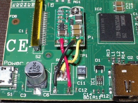
[Karl Lunt] is working to slim the Raspberry Pi current draw as much as possible. The first step in his journey was to replace the linear voltage regulator with this switch mode version. It’s a step-down voltage regulator circuit with a tiny footprint and a matching price tag (about $10) made by Pololu. It’s small enough to be mounted in the empty space between the LCD ribbon connector and the main processor.

The project was based on the hack we saw at the end of June. But we give much more credit to [Karl] for removing the old part in a safer way. He clipped the two small leads on the bottom of the old part, then used a beefy iron to sufficiently heat the large pad before removing the body of it. With the old part out of the way it’s just a matter of connecting the three wires in the right configuration.

This cut consumption by about 50 mA. He’s hoping to do more by removing the on-board LEDs. His goal is a draw of under 250 mA in order to make it last a reasonable amount of time when running from batteries.

Acrylic RPi Case You Can Make Without A CNC Machine

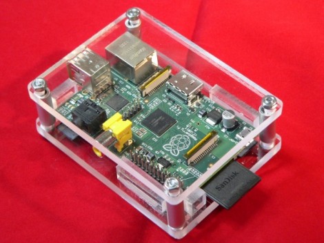
[Simon Inns] is showing off the Raspberry Pi case which he built out of acrylic. It provides a lot more protection than a flimsy film case, but it is also a little bit more involved to fabricate. No, this doesn’t need to be laser cut, but to get the nice edges [Simon] used a band saw which many don’t already have in their shop. Ask around, or poke your head in at the local Hackerspace. It only takes a few minutes to cut out the parts.

It sounds like either 8mm or 6mm acrylic will work for this project. Aluminum pipe serves as a spacer to keep the two main sheets in place. The RPi board itself is held in position by a few well-place acrylic chunks super glued in place. You can see the entire build process, including rounding cut edges with a torch, in his video embedded after the break.

Continue reading “Acrylic RPi Case You Can Make Without A CNC Machine”

Flimsy Pi Case Still Provides A Level Of Protection

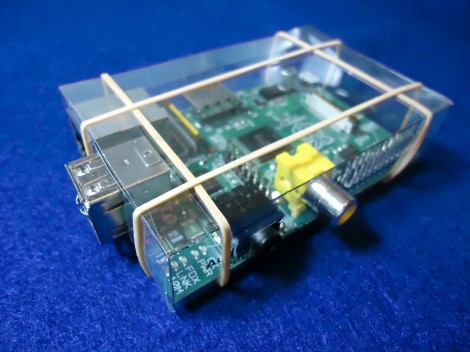
This flimsy case isn’t going to protect your Raspberry Pi if you knock it off the workbench. It will provide a level of protection against shorting out from contact with metal objects, or from liquids spilled in the near vicinity. [CGPatterson] ended up making this case from a single sheet of transparency film.

The project is basically papercraft. He started with the dimensions published on the Raspberry Pi FAQ, which turned out to be wrong. Not having a caliper available to help with the precision of the measurements, he grabbed his ruler and did the best he could. The first two cases were a poor fit, but as you can see the third is like a glove. Luckily you don’t have to go through this same trial and error as he release the design. Both A4 and US Letter sized PDFs are available for download. Print them out on the transparency, cut along the lines, apply transparent double-sided tape to the tabs and you’re in business. If you wish to alter the design he has also posted the SVG source he made in Inkscape.

This is certainly a good option for those of us without the ability to produce laser cut parts.

Interfacing SNES Controllers With Your Raspberry Pi

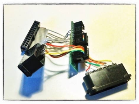
This lovely set of wires lets [Florian] connect stock Super Nintendo controllers to his Raspberry Pi. The IDC connector in the upper left plugs into the GPIO header on the RPi rather than going the route of using an intermediary USB converter.

The setup lets you connect two controllers at once, so you’ll have no trouble going head-to-head on Mario Kart as seen in the clip after the break. The ports themselves were pulled from a pair of SNES extension cables. Since button signals are pushed to the console via a shift register there’s just five wires needed for each (voltage, ground, data, clock, and latch). As far was we know the Raspberry Pi pins are not 5V tolerant so you probably want to add some level conversion to this circuit if you build it yourself.

[Florian] wrote a C program which shifts in data from the controllers and converts it to HID keyboard inputs. This should make it extremely flexible when it comes to emulator setup, and using the technique for different styles of controllers should also be pretty easy.

Continue reading “Interfacing SNES Controllers With Your Raspberry Pi”

Raspberry Pi Controlled Tank Goes Deeper Than You Might Think

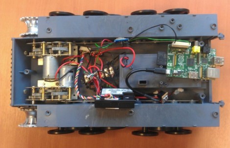
This remote control tank now takes its orders from a Raspberry Pi board. Well, actually it’s taking orders from commands pushed to the RPi board via SSH. The control scheme works out quite well. Using a low-profile WiFi dongle the RPi automatically connects to the wireless network when it is powered on. This makes it a snap to SSH into the device, and a more user-friendly controller will put a nice front-end into play at some time in the future.

But the real meat and potatoes of the hack comes in getting the RPi to talk to the tank’s circuitry. Just getting the Heng Long Tiger I remote control tank apart proved to be a ton of work as the treads need to be removed to do so and there’s a lot of screws holding it together. Instead of just replacing all of the control circuitry [Ian] wanted to patch into the original controller. To do so he spent a bit of time analyzing the signals with an oscilloscope and discovered that commands were coming in a Manchester encoded format. He established what various packets were doing, used a transistor to protect the GPIO pin on his board, and now has full control of the Tank. The final part of the hardware alteration was to power the RPi from the Tank’s battery.

After the break you can catch a demo of the reassembled tank sporting its new wireless controller.

Continue reading “Raspberry Pi Controlled Tank Goes Deeper Than You Might Think”

Raspberry Pi Power Regulator Transplant Reduces Power Consumption

If you want to run your Raspberry Pi from something other than a mains power converter, and you’ve got some courage to spare, this hack is right up your alley. [Tom] wrote in with a switch mode power replacement for the RPi’s stock linear regulator. This is the first hack we’ve seen where the RPi’s on-board hardware is being altered and that’s where things get a little scary.

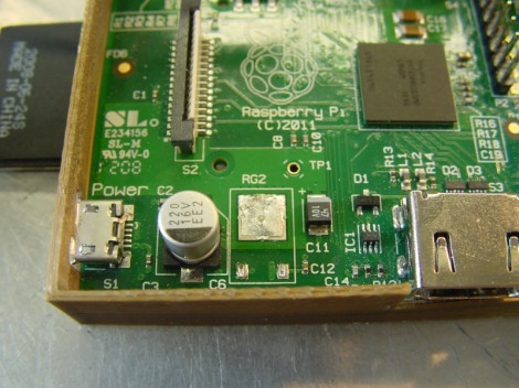
The first thing done was to remove the linear regulator, leaving the unpopulated RG2 footprint seen above. Apparently a rework station wasn’t available as the technique they used describes holding the board up by gripping the regulator with tweezers, then blasting it with a hot air gun. It makes us a bit queasy because the processor chip has a solder footprint you don’t want to mess with.

But apparently all is still well. With the wasteful linear regulator gone a pair of 5v and 3.3V switch regulators inject voltage through the GPIO header. Initial tests show a savings of around 25% but we’d imaging this varies greatly based on load.

Using An HD44780 Character LCD With The Raspberry Pi

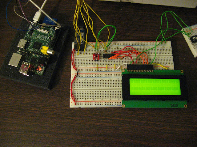
[Tech2077] is one of the lucky ones who already got his hands on a Raspberry Pi. He’s been looking into different interface options with the GPIO header and just posted a guide to using an HD44780 character display with the RPi. We like this approach because instead of doing some hard-core LCD work he’s using prototyping equipment you probably already have on hand.

Getting a character LCD running should be really simple. The gotcha is the logic level gap between the devices. If you’ve been working with Arduino, your add-ons are probably meant for a 5V power rail  and logic levels. The RPi outputs 3.3V logic. You could use a level converter (you’d need at least 7 pins to be converted in this case) or you can be a bit more clever. [Tech2077] grabbed an I2C port expander that uses just 2 of the RPi lines to address even lines of the display (four data bits plus three control bits). This is a bit of a hack, as the 3.3V logic is 0.2V below the recommended minimum for a digital 1 on the port expander. But it seems to work just fine! If it didn’t, a couple of NPN transistors would do the trick as well.

Addressing the new peripheral is just a matter of loading the i2c module and writing some Python.