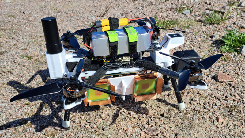
It’s been more than a year since [Henrik Forstén] built the first iteration of his synthetic-aperture radar (SAR) imaging drone, and he’s certainly been productive in the meantime. Not only did he develop a much more powerful autofocus algorithm to clean up the radar images, but he also extended the software to create high-resolution interferometric images.
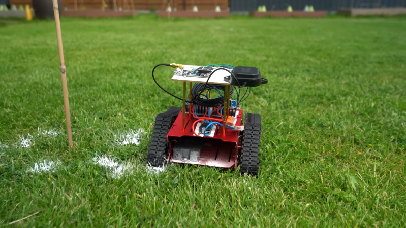
The main limitation of the original radar system was the GPS, which only had a resolution of about one meter; the autofocus algorithm owed much of its improved clarity to an improved estimation of the drone’s position. A simpler, though more expensive, solution was to add an RTK-capable GPS receiver. RTK (Real-Time Kinematic) receivers use a fixed ground station to constantly transmit a correction signal, letting them reach a couple centimeters of accuracy. Since the drone doesn’t actually need to know its position in real time, it can also use PPK (Post-Processing Kinematic) positioning, which compares recorded GPS signals after the flight to obtain similarly accurate positions.
[Henrik] also implemented a few other hardware improvements, including stabilizing the phase-locked loop used to generate the radar’s frequency sweep. The controller FPGA’s SD card interface had too low a bandwidth to record data in real time, so [Henrik] also implemented a simple, fast compression algorithm to speed that up. Most significantly, he also developed a program for interferometric imaging. The drone flies the same path twice at different altitudes; by comparing phase information from different passes, it’s possible to detect a target’s elevation. Normally, the radar program assumes constant elevation, making tall objects seem to lean toward the radar source; an interferogram, on the other hand, allowed [Henrik] to generate a detailed elevation map.
[Henrik] is no stranger to synthetic aperture radar; we’ve previously covered a bike-mounted iteration and a budget SAR system. If the concepts behind this are still a bit fuzzy, we’ve also covered a guide to making your own SAR setup.