What The Flux: How Does Solder Work Anyway?

I’ve been soldering for a long time, and I take pride in my abilities. I won’t say that I’m the best solder-slinger around, but I’m pretty good at this essential shop skill — at least for through-hole and “traditional” soldering; I haven’t had much practice at SMD stuff yet. I’m confident that I could make a good, strong, stable joint that’s both electrically and mechanically sound in just about any kind of wire or conductor.

But like some many of us, I learned soldering as a practical skill; put solder and iron together, observe results, repeat the stuff that works and avoid the stuff that doesn’t. Seems like adding a little inside information might help me improve my skills, so I set about learning what’s going on mechanically and chemically inside a solder joint.

Continue reading “What The Flux: How Does Solder Work Anyway?”

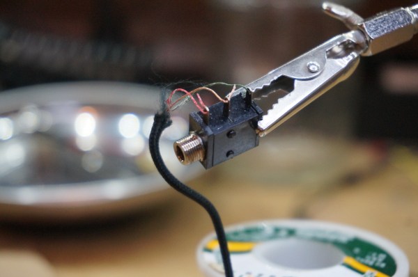
Iron Tips: Soldering Headphones And Enamel Wire

We’ve all had that treasured pair of headphones fail us. One moment we’re jamming out to our favorite song, then, betrayal. The right ear goes out. No wait. It’s back. No, damn, it’s gone. It works for a while and then no jiggling of the wire will bring it back. So we think to ourselves, we’ve soldered before. This is nothing. We’ll just splice the wire together.

So we open it up only to be faced with the worst imaginable configuration: little strands of copper enamel wire intertwined with nylon for some reason. How does a mortal solder this? First you try to untwine the nylon from the strands. It kind of works, but now the strands are all mangled and weird. Huh. Okay. well, you kind of twist them together and give a go at soldering. No dice. Next comes sandpaper, torches, and all sorts of work-a-rounds. None of them seem to work. The best you manage is sound in one ear. It’s time to give up.

Soldering this stuff is actually pretty easy. It just takes a bit of knowledge about how assembly line workers do it. Let’s take a look.

Continue reading “Iron Tips: Soldering Headphones And Enamel Wire”

Hackerspace Takes Fume Extraction Seriously

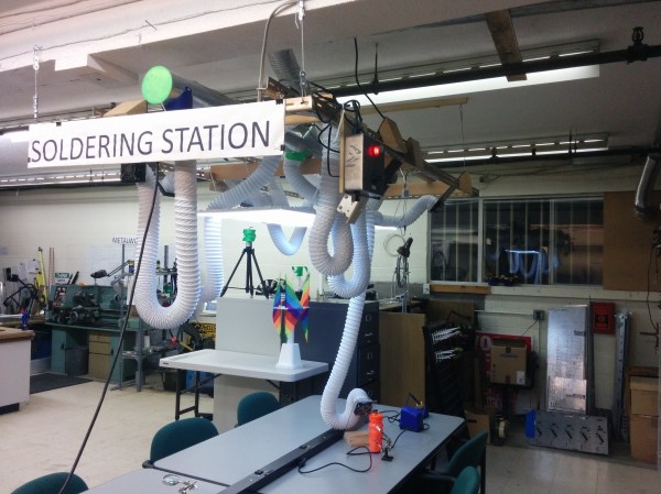
At first we laughed at the ridiculously over-the-top fume extraction system this hackerspace built for itself. Then we thought about seriously questionable donation rolls of solder some of the members managed to find and bring in. The kind of roll where the local greybeard assures you that a Californian State Trooper has permission to shoot you if you try to take it into the state, but damn does it solder well. They may be onto something is all we’re saying. But on a serious note, for a communal space like this one, a great air quality plan makes the place a lot more pleasant, if not safer at the same time.

The build uses a regular boost fan for its main suction and pulls the fumes out to a place the members aren’t. Knowing hackerspaces that could be anything from an empty alley to vents on the building’s roof. It’s actually an interesting challenge to solve in a rented space (please share your own solutions for “daylighting” to the outside in the comments).

The frame is made from ducting and dryer hose. Since there aren’t really fittings for this. Most of the joints were designed in OpenSCAD and 3D printed. At each end of the tube a computer fan provides another little boost of airflow. We like the stands to position each end of the hose at the fume source. All of it is powered by a distribution box of their own making with the juice being fed with repurposed Ethernet cables to the fans at the ends of the hose.

It’s a nice build and likely extended the life of a few of the more electronically active members in the space. Especially if the retired radio enthusiasts decide to do their fifty year anniversary garage cleaning and gift upon the space their findings.

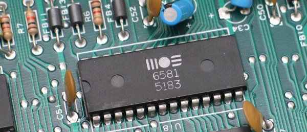
By Christian Taube - Own work, CC BY-SA 2.5, https://commons.wikimedia.org/w/index.php?curid=1503038

Tools Of The Trade – Through Hole Assembly

In our last installment of Tools of the Trade, we had just finished doing the inspection of the surface mount part of the PCB. Next in the process is the through hole components. Depending on the PCB, the order may change slightly, but generally it makes more sense to get all the SMT work done before moving to the through hole work.

Through hole used to be the standard, but as the need for size reduction and automation increased, SMT gained favor. However, there are still a lot of reasons to use through hole components, so they aren’t going away entirely (at least not any time soon). One of the biggest advantages of THT is mechanical strength, which makes it better suited for connectors than SMT. If you’ve ever popped a microusb connector off a PCB by breathing on it heavily, you’ll understand. So, how do we most efficiently get through hole components on a PCB, and how do the big boys do it?

Continue reading “Tools Of The Trade – Through Hole Assembly”

Ask Hackaday: How Hard Is It To Make A Bad Solder Joint?

When you learn to solder, you are warned about the pitfalls of creating a solder joint. Too much solder, too little solder, cold joints, dry joints, failing to “wet” the joint properly, a plethora of terms are explained  if you read one of the many online guides to soldering.

Unsurprisingly it can all seem rather daunting to a novice, especially if they are not used to the dexterity required to manipulate a tool on a very small-scale at a distance. And since the soldering iron likely to be in the hands of a beginner will not be one of the more accomplished models with fine temperature control and a good tip, it’s likely that they will experience most of those pitfalls early on in their soldering career.

As your soldering skills increase, you get the knack of making a good joint. Applying just the right amount of heat and supplying just enough solder becomes second nature, and though you still mess up from time to time you learn to spot your errors and how to rework and fix them. Your progression through the art becomes a series of plateaux, as you achieve each new task whose tiny size or complexity you previously thought rendered it impossible. Did you too recoil in horror before your first 0.1″ DIP IC, only to find it had been surprisingly easy once you’d completed it?

A few weeks ago we posted a Hackaday Fail of the Week, revolving around a soldering iron failure and confirmation bias leading to a lengthy reworking session when the real culprit was a missing set of jumpers. Mildly embarrassing and something over which a veil is best drawn, but its comments raised some interesting questions about bad solder joints. In the FoTW case I was worried I’d overheated the joints causing them to go bad, evaporating the flux and oxidising the solder. This was disputed by some commenters, but left me with some curiosity over bad solder joints. We all know roughly how solder joints go wrong, but how much of what we know is heresay? Perhaps it is time for a thorough investigation of what makes a good solder joint, and the best way to understand that would surely be to look at what makes a bad one.

Continue reading “Ask Hackaday: How Hard Is It To Make A Bad Solder Joint?”

“I Can Reflow” Merit Badge

[Nick Sayer] can reflow, and he can prove it. He designed a simple blinking-LED circuit that uses SMD parts to, well, blink LEDs. That’s not the point, though. It’s designed to be a test platform for reflow soldering, and to use a minimum number of valuable parts. Plus, it says “I can reflow!” in exposed copper. What else do you want?

OK, as far as “proving it” goes, the badge isn’t 100% reliable — we hand-solder 0805 components all day long. But still, if you want to try your hand at reflowing a circuit board, and you don’t want to ruin a lot of expensive parts if you fail, something like this is a good idea.

The design is open, and it’s really the idea that’s the point here anyway. How about something that would be really onerous to hand-solder, but still cheap? We’re thinking a matrix of tiny LEDs and a shift register or something.

We just ran an article on a hand-soldering challenge board, this seems the perfect complement. Display both proudly on your desk and confound and amaze your coworkers!

Tools Of The Trade – Reflow

In our previous issues in this series on making circuit boards, we covered placing solder paste and placing components. Now it’s time to bake our cake!

There are a variety of methods for reflowing a circuit board, but they all rely on a single principle: heat up the solder paste (a mixture of flux and solder) until the flux burns off and the solder becomes liquid, and then cool it down. Accomplishing this once or twice is easy; once you’ve played with a hot plate you’ll swear off through hole. Scaling it up and doing it repeatedly with high yield is extremely challenging, though. Continue reading “Tools Of The Trade – Reflow”