Linux audio may be confusing for the uninitiated. As a system that has evolved and spawned at least two independent branches over time it tends to produce results that surprise or irritate the user. On the other hand it is open source software and thus can be fixed if you know what you do.
Over at reddit [rener2] was annoyed by the fact that listening to music on his laptop was a significantly worse experience under Linux than under Windows. Running Windows the output of the headphone jack covered the whole spectrum while his Linux set up cut off the low end resulting in a tinny sound. The culprit in this is the sound card: it has two different output paths for the internal speakers and the headphone jack. The signal for the internal speakers is routed through a high pass filter to spare them the embarrassment of failure to reproduce low frequencies.
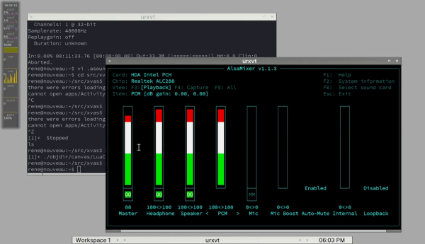
When headphones are plugged in, the sound card driver is supposed to make the sound card bypass the filter and deliver the full spectrum. The authors of the Windows driver knew this and had it taken care of. In his video [rener2] runs us through the process of patching the ALSA driver while referencing the documentation of a sound card that he deems ‘similar enough’ to his Realtek ALC288.