Manga Guide To SMD

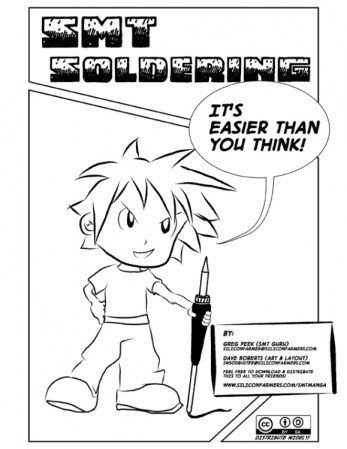
For those that have always felt a bit treppidatious when approaching SMD, you can relax. Here’s a simple guide to walk you through your first shaky steps into surface mount devices. Distributed freely under the creative common license, the Manga Guide to SMD is an 18 page comic that has a goal of making SMD producers out of all of us. There’s a good visual explanation of what SMT is and why we use it, as well as a thorough walk through of how to solder the tiny devices with your soldering iron. They don’t go into dealing with a small reflow oven in this issue.

If this fits well with your learning style, you might also be interested in the Manga Guide to Electricity.

SMDuino Helps Arduino Fit Into Tight Places

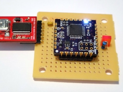
[Adam] was tired of plopping the same components over and over into his Arduino-based designs. He spent part of his weekend laying out a small board that would host everything he needed and could be built as a single component for all future projects. Above you can see the project he calls SMDuino, an Arduino clone that can be used as a surface mount part.

The contacts on four sides of the board break out the pins. They’ve been designed with 0.1″ pitch which means they will work with standard pin headers. But since they’re plated through from top to bottom they are easy to solder to surface mount pads as well. The project is open source, so you can order your own boards (he used DorkBot PDX) or email him if you want to get in on a pre-order. That is for unpopulated PCBs only. But there’s few components used here so it’s pretty inexpensive to throw together. You’ll need four caps, four resistors, a crystal, an LED, the ATmega*8 of your choice (an ATmega328 is used here), and a low dropout regulator. Of course it is possible to go without the crystal oscillator.

Does this remind anyone else of the Basic Stamp 2?

Fine-pitch SMD Soldering With Minimal Tools

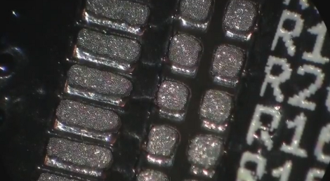
We try to stick to the 0805 parts because they’re still big enough to solder by hand. But [Scott] shows us that it doesn’t take too many special tools to reflow fine-pitch components at home. In this case he’s using 0402 resistors, a footprint that we consider functionally impossible to solder using an iron.

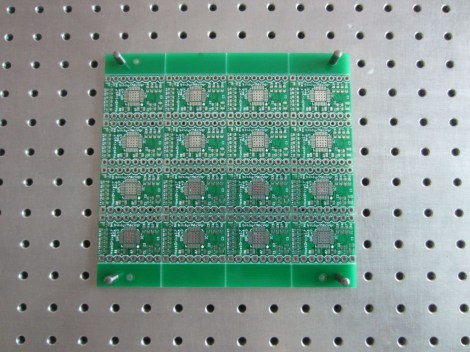
The two parts of the equation that he spent some money on are professionally produced PCBs and a solder stencil. The stencil is laser-cut from Kapton, which is heat-resistant so it doesn’t warp during the cutting process. An acrylic frame holds the PCB in place, and he just tapes the stencil over it and uses a chunk of acrylic as a squeegee to evenly apply the solder paste. Splurging on the PCB and stencil means you’ll achieve tolerances which lead to success.

The next issue is placing the components. [Scott] shows off some vacuum tweezers he built using an aquarium pump. Watch the video after the break to see how small those 0402 parts are when he extracts one of the resistors from the tape packaging. With the board manually populated (check everything twice!) he moves the board to a completely unaltered toaster oven for reflow. We have seen a lot of projects which add controllers to these ovens, but he really makes the case that you don’t need it. Instead, he uses a thermocoupler read by a multimeter just to let him know what’s going on with the temperature. He uses a smart phone as a timer, and switches the oven on and off to match the solder’s heat profile. Continue reading “Fine-pitch SMD Soldering With Minimal Tools”

How To Etch Your Own Solder Paste Stencils

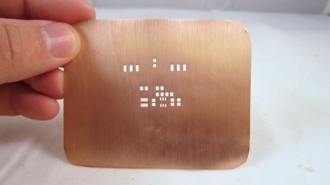
We’re kind of surprised we haven’t covered this concept before since it only uses techniques that are commonly avaialable for home PCB fabrication. [Ray] made this solder paste stencil out of a sheet of copper using the same etching techniques you would for a circuit board. He designed and printed a resist pattern, with toner everywhere except the places where there should be holes in the stencil. He transferred the toner to the copper using an iron.

The difference here should be obvious; this a thin copper sheet with no substrate. Because of that, you must protect the copper surface before etching. he covered the entire thing, both sides, in packing tape. After that it’s into the Cupric Chloride bath to dissolve the exposed parts. Once the tape and toner has been removed you can scree a precise amount of solder paste onto your boards.

This isn’t for everyone, but if you’re assembling many boards it’s not a bad approach. If the stencil is no longer used it can be recycled, but we do wonder how corrosion on the copper will affect the stencil’s performance.

The idea for this technique came to [Ray] from a guide that’s been around for years.

Surface Mount Solder Assitant

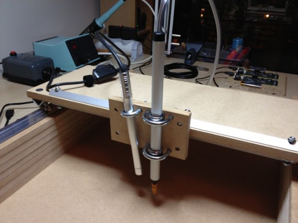
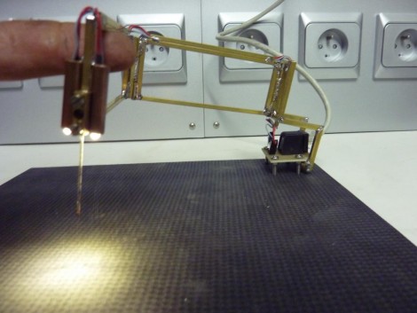
Make sure those tiny parts know their place by using this surface mount solder assistant (translated). It’s like a clamp for small packages; gravity and a needle to hold them in place while you do some hand soldering. [Red Devil] started the built by soldering together some brass rails into a hinged frame with a clamp to accept the needle tip. Next, a pair of tubes were added to accept LEDs which light the work area (we think that’s a fantastic touch). Finally, the assembly was mounted to the corner of a square base that makes up the work surface.

This is basically a complex version of a simple gravity clamp. But if you’re doing some assembly line soldering this would be indispensable. For this kind of work, custom jigs are often built. That would still be the case, but this armature removes the need of building something into each jig to hold the SMD components in place.

Which Resistor Values Should You Order For All Circumstances?

A hard drive crash, and some other happenings that aren’t entirely clear to us, led [Devbisme] to put in a parts order. As he wanted to make the most of his shipping costs, he decided to fill out the order with parts that he’ll use eventually. He’s been working with surface mount designs and wanted to move from using resistors with 0805 packages to the 0603. Having nothing on hand, he devised a way to account for almost all standard values with the fewest number of different resistors.

That’s a mouthful, but what he actually did was figure out what combinations of resistors can best be wired in parallel to achieve a different standard resistance value. This way, if he doesn’t have a specific value he can solder one 0603 surface mount resistor on top of another one to get there. He ended up writing a Python program to best calculate this set of values. It came up with a set that lets him synthesize 159 of the 168 standard resistor values within +/- 4% using just 19 actual resistor values. His method requires anywhere from one to three resistors to get to each value. Soldering three 0603 packages on top of each other might not be the most fun, but it makes for easy parts inventory management.

POV Keychain From Prototype To SMD Board

[Augusto] wrote in to tell us about his keychain-sized persistence of vision project. He built the original prototype on some protoboard, using a PIC 16F627 to drive eight LEDs. Synchronization is managed by a tilt sensor on the board that starts the strobing to match the direction the board is traveling. This is a similar setup as the POV device that used an accelerometer, but it should be quite a bit easier to code for the tilt switch.

Once [Augusto] had the hardware dialed in he set to work laying out a surface mount design. The two AAA batteries were traded for a single 3V coin cell, which is on the back side of the board you see above. This is his first attempt at working with surface mount components and we think he did a great job. Check out the POV in action in the video after the break.

Continue reading “POV Keychain From Prototype To SMD Board”