One-man SMD Assembly Line Shares A Lot Of Tips About Doing It Right

Need to use that antiquated hardware that can only be connected via a parallel port? It might take you some time to find a computer that still has one of those, or you could try out this USB to Parallel port converter. It’s not limited to working with printers, as the driver builds a virtual parallel port that you should be able to use for any purpose. But what we’re really interested in here isn’t the converter itself, but the build process. [Henrik Haftmann] posted a three-part series of videos on the assembly process, which you can watch after the break.

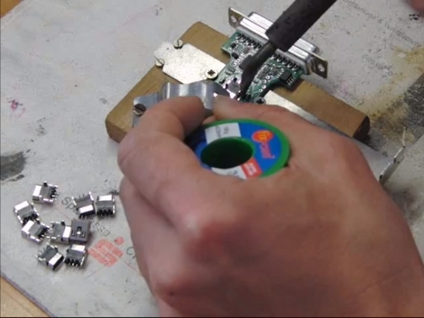
The build is mostly surface mount soldering with just a handful of components that need to be hand soldered. The first of his videos shows him stenciling solder paste onto the boards. From what we can see it looks like he built a nice jig for this using scrap pieces of copper-clad which match the thickness of the PCB, and hold it and the stencil securely in place. There’s a bunch of other tips you can glean from the videos, like the image seen above. It’s a clamp that holds the PCB and USB jack together while they are soldered.

If you’re ever thinking of assembling a bunch of boards you should set aside thirty minutes to watch them all.

Continue reading “One-man SMD Assembly Line Shares A Lot Of Tips About Doing It Right”

Kapton Tape Aids In Drag Soldering Surface Mount Parts

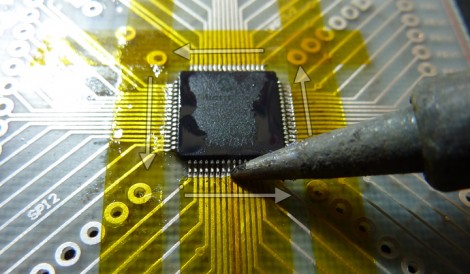
Drag soldering works exactly as its name implies, by dragging a bead of solder across fine-pitch pins you can quickly solder an entire row. The method relies on clean joints, so liquid solder flux is often used to make sure there is good flow. But if you’re drag soldering on boards that you’ve etched yourself the solder can sometimes run down the trace, rather than staying where you want it. Professionally manufactured boards don’t have this problem since they have solder mask covering the copper that doesn’t need soldering. [Ahmad Tabbouch] has a method that uses Kapton tape to act as a temporary solder mask on diy boards.

The process involves several steps. First, three strips are place horizontally across the board, leaving just a portion of the upper and lower pads exposed. Those pads are then tinned with solder, and a light touch with an X-acto knife is then used to score the tape covering the vertical rows of pads. Once the waste as been removed, two more strips are added and those rows are tinned. From there the chip is placed and soldered as we’ve seen before; first tacked in place, then fluxed, and finally drag soldered to complete the connections. This achieves a crisp and clean connection, presumably without the need to clean up your solder mess with solder wick.

Kapton tape resists heat, making it perfect for this process. We’ve also seen it used on hot beds for 3D printers, and as a smoothing surface for sliding mechanisms.

[via Dangerous Prototypes]

Cutting Out Your Own Breakout Boards

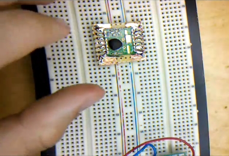
[Caleb] needed to use some surface mount components when prototyping. Instead of buy a breakout board he made one himself without doing any etching. The process he shows off in the video after the break uses copper tape to layout the traces for the board. It’s quite an interesting method which requires a sharp knife and a steady hand.

He used regular protoboard as a substrate and applied a layer of copper tape on the side without copper pads. From there he poked holes for the DIP pin headers. Now it’s time to do some cutting. [Caleb] removed the band of copper that would fall in between the pins of the surface mount device. He then tacked it in place with one dot of solder and drew the traces from the part to the pin headers. After removing the part he cut out the waste in between each line he drew with marker. What he’s left with is a set of thin traces that connect each pin of the surface mount component to the corresponding through-hole pin header.

This is very time-consuming, but then again so is soldering jumper wires to small-pitch components.

Continue reading “Cutting Out Your Own Breakout Boards”

DIY Clamp Helps With Surface Mount Soldering

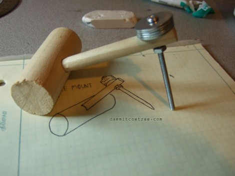
Hackaday writer [Gerrit Coetzee] built a simple clamp to aid in surface mount component soldering. This cheap, easily made device uses gravity to hold tiny components in place. The tip of the bolt is pointed, but gently like a ballpoint pen so as not to harm the components with a sharp tip. Roughly position your component, rest the tip of the clamp on its center, then nudge for final positioning. [Gerrit] also points out that this acts as a heat sink, helping to prevent damage to the component if you’re too lethargic with the soldering iron.

It seems like this device has been around in one form or another for quite a long time. But the best ideas do keep on popping up. Another nice tip to go along with this one is the use of a dowel when ironing during toner transfer for your PCBs.

Skillet Reflow Controller

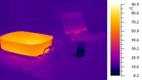
Using an electric skillet to reflow surface mount circuit boards is a popular alternate use for those kitchen appliances. The real trick is monitoring and controlling the temperature. [Mechatronics Guy] built his own skillet temperature controller using a thermistor, a solid state relay, and an Arduino.

He was inspired by [Ladyada’s] work which used a servo to adjust the temperature dial on the skillet’s power supply. This started by attaching the thermistor to the bottom of the skillet using JB weld. since this area will be heating up he also attached a terminal block for connecting the feed wires as the heat would melt any solder joints. Those wires travel back to a control box housing the Arduino and solid state relay. To gain finer control over the heating element the relay is switched on and off, resulting in low-frequency Pulse Width Modulation, which should help maintain a consistent temperature better than just turning the temperature dial on the cord.

Pair this up with the vacuum tweezers hack and you’re on your way to a surface mount assembly line. If you want to see this process in action check out this post. It goes from stenciling, to populating, to reflowing in a toaster oven.

[Thanks Rob]

Surface Mount Breakout Boards

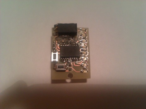
We got a hold of some DS3232 RTC chips in a 20-pin SOIC package. We’d like to have one that is breadboard compatible for easy prototyping but when we searched for SOIC20W breakout board artwork we found none. We used Eagle to design our own and you can see the finished product above which we made using the toner transfer method and cupric chloride.

You’ll find the artwork after the break in case you need to make your own breakout board some day. If you know of surface mount breakout board artwork that is freely available please leave the link in the comments for future use, or send it to us on our tips line and we’ll add it to the post.

Incidentally, the DS3232 is the same as the DS3231 used in the ChronoDot but with the addition of some SRAM. We’ll let you know if we come up with an interesting project for it.

Update: We added 28 SSOP to DIP artwork submitted by [Paul Dekker]

Continue reading “Surface Mount Breakout Boards”

Laser Cutting Solder Stencils

Do you have access to a laser cutter? If so, you can use [Riley Porter’s] method to cut your own solder stencils. He starts with the Eagle files and exports the Dimension and tCream layers to a PDF. That file is then processed using Ghostwriter, Gview, and finally, Corel draw. The result is a 1200dpi file to feed to your Epilog laser. Now you’re ready to stencil on the solder paste and populate the PCB.

[Thanks Travis Goodspeed]