Digital Decade Resistance Box On The Cheap

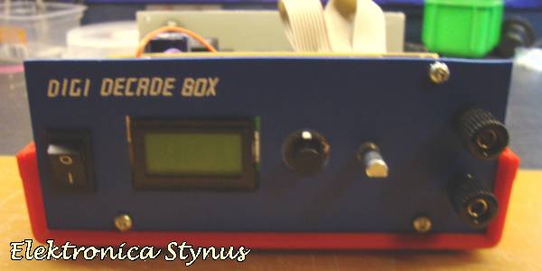
[Stynus] has finished a unique decade resistance box which doesn’t use conventional rotary switches to select the appropriate resistors. These switches are old fashioned and expensive, so [Stynus] built this decade resistance box that uses a microcontroller and a series of relays to switch the resistors.

Simply selecting a resistance on the screen tells the microcontrollers which resistors need to be switched in order to provide the proper resistance. The box uses relays to do switching instead of transistors because the transistors don’t handle high frequency AC as well as the relays. The device is powered by an 18V transformer and rectifier and, as a bonus, [Stynus] got all of his parts on the cheap which made this a great solution to the expensive resistance decade box problem.

This is a very well-polished piece of test equipment. We’ve featured other decade resistance boxes but never one that was controlled by a microcontroller. All of the PCB layouts and the code for microcontroller are available on the project site if you have a desire to make your own.

GPIB To USB, With A Python API

If you’re not so daft as to think Arduino-based oscilloscopes and multimeters are actually useful for all but the simplest tests and measurements, you just might have some big iron sitting around your workbench from the likes of HP, or Tektronix. You might have noticed a strange port on the back of these machines, labeled GPIB or IEEE-488. This is the standard interface for these devices, and if you’ve ever priced out a USB to IEEE-488 converter, you can see why [Steven] thought it would be cheaper to build his own.

This build is an update to an earlier version we saw a few years ago. Since then, [Steven] has taken some advice from the community and replaced a bunch of resistors with proper GPIB line driver ICs, and generally cleaned up the firmware.

Because a USB to GPIB adapter is only one small part of the tools necessary to connect these old measurement devices to a modern computer, [Steven] has also been working on InstrumentKit. It’s a Python library that takes all the standardized instrument commands and wraps them up in an easy to use API. You can check out the docs for InstrumentKit here, or just look through the board files and firmware on the Github

Rebuilding A Custom IC Saves HP Pulse Generator


Rebuilding an HP Custom IC
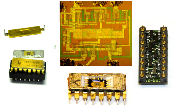
[Matthew] got himself into a real pickle.  It all started when he was troubleshooting a broken Hewlett Packard 8007A pulse generator. While trying to desolder one of the integrated circuits, [Matthew] accidentally cracked it. Unfortunately, the chip was a custom HP Pulse shaper IC – not an easy part to source by any means. That broken chip began a 5 year mission: to explore strange new repair methods. To seek out new life for that HP 8007A. To boldy fix what no one had fixed before.

[Matthew’s] first repair attempt was to build a drop in replacement for the HP chip. He took a look at the block diagram, and realized the chip was just some simple logic gates. He built his version with a small PCB and Fairchild TinyLogic gates. Unfortunately, the TinyLogic series is fast CMOS, while HP’s original chip used Emitter-coupled Logic (ECL). Thanks to the wildly different voltage levels of the two logic families, this design had no chance of working.

Five years later, [Matthew] was going to school at MIT, and had access to a wire bonding machine. He rebuilt the package using some epoxy, and managed to re-run the various bond wires. While everything looked promising, this attempt was also a failure. After all that work, the chip was blown.

Continue reading “Rebuilding A Custom IC Saves HP Pulse Generator”

A USB Connected Box-o-Encoders

picoscope-encoder

[Colin] loves his PicoScope, a USB based “headless” oscilloscope. While using it he found himself longing for a classic oscilloscope interface. Mouse clicks just weren’t a replacement for grabbing a dial and twisting it. To correct the situation he created his USB-Connected Box-o-Encoders. The box maps as a USB keyboard, so it will work with almost any program.

[Colin] started by finding encoders. There are plenty of choices – splined or flatted shaft, detents or no detents, panel, PCB, or chassis mount. He settled on an encoder from Bourns Inc. which uses an 18 spline shaft. His encoder also includes a push button switch for selection. With encoders down, knobs were next. [Colin] chose two distinct styles. The two knob styles aren’t just decorative. The user can tell which row of knobs they are on by touch alone. Electronics were made simple with the use of a Teensy++ 2.0. [Colin] used a ATUSBKey device running Teensy software, but says the Teensy would have been a much better choice in terms of size and simplicity.

Once everything was wired into the box, [Colin] found his encoders would “spin” when the knobs were turned. They are actually designed to be PCB mounted, and then screwed into a control panel. Attempts to tighten down the panel mounting nut resulted in a broken encoder. Rather than redesign with purely panel mounted encoders, [Colin] used a dab of epoxy to hold the encoder body in place.

Continue reading “A USB Connected Box-o-Encoders”

Hackaday Links: January 12, 2014

hackaday-links-chain

[Kyle] teaches photography and after being dismayed at the shuttering of film and darkroom programs at schools the world over decided to create a resource for film photography. There’s a lot of cool stuff on here like mixing up a batch of Rodinal developer with Tylenol, lye, and sodium sulphite, and assessing flea market film cameras. There are more tutorials coming that will include setting up a dark room, developing prints, and playing around with large format cameras.

[hifatpeople] built a binary calculator out of LEGO® bricks or toys. It started off as a series of logic gates built out of LEGO® bricks or toys in the LEGO® Digital Designer. These logic gates were combined into half adders, the half adders combined into full adders, and the full adders combined into a huge plastic calculator. Unfortunately, buying the LEGO® bricks or toys necessary to turn this digital design into a physical model would cost about $1000 using the LEGO® Pick-A-Brick service. Does anyone have a ton of LEGO® Technic® bricks or toys sitting around? We’d love to see this built.

Think you need a PID controller and fancy electronics to do reflow soldering in a toaster oven? Not so, it seems. [Sivan] is just using a meter with a thermocouple, a kitchen timer, and a little bit of patience to reflow solder very easily.

The folks at DreamSourceLabs realized a lot of electronic test equipment – from oscilloscopes and logic analyzers to protocol and RF analyzers were all included a sampling circuit. They designed the DSLogic that puts a sampler and USB plug on one board, with a whole bunch of different tools connected to a pin header. It’s a pretty cool idea for a modular approach to test equipment.

Adafruit just released an iDevice game. It’s a resistor color code game and much more educational than Candy Crush. With a $0.99 coupon for the Adafruit store, it’s effectively free if you’re buying anything at Adafruit anytime soon. Check out the video and the awesome adorable component “muppets”.

Adorable Homebrew Waveform Generator

waveform

For want of new test equipment, or simply a project, [Enzo] decided he would take a shot at creating his own waveform generator*. Not only is it a great project, it’s also a decent piece of test equipment, with proper signal conditioning, a nice front panel, and a built-in wall transformer.

The guts of [Enzo]’s waveform generator is an AD9833 programmable waveform generator, a neat little chip that can output square and triangle waves fro 0.1 Hz to 3.2 MHz and sine waves from 0.1 Hz to 1.6 MHz. [Enzo] is controlling this chip with a PIC16 microcontroller, with a whole bunch of analog circuitry between the digital domain and the BNC connector on the front panel.

The waveform generator is controlled by a suite of dials and switches on the front panel, giving [Enzo] complete control over his new tool.

* Here’s a Google translation, but good luck with that. Just… get Chrome or something.

Voltage Logger Does It The Right Way

testing

The folks over at Adafruit have been busy designing an LED matrix wristwatch for a while now. The circuit works great, but since this watch is powered by a coin cell battery, they’d really like to get the power consumption as low as possible. This means they needed a test rig to measure the consumption of each firmware revision, but how exactly do you build a voltage logger that works with voltages and currents this small? It turned out to be a very interesting project, with plenty of info on how to build an accurate voltage logger for really small projects.

Continue reading “Voltage Logger Does It The Right Way”