TDS 744A Scope Teardown Fixes Dodgy Channel

There are a lot of oscilloscopes from around the 1990s which are still very much desirable today, such as the Tektronix TDS 744A which [DiodesGoneWild] got his grubby mitts on. This is a 500 MHz, 4-channel scope, with a capture rate of 500 MS/s (4 channels) to 2 GS/s (1 channel). It also has a color display and even comes with a high-density (1.44 MB) floppy drive. Unfortunately this particular unit was having trouble with its fourth channel, and its NuColor display had degraded, something that’s all too common with this type of hybrid CRT/LCD (LCCS) technology.

Starting with a teardown of the unit to inspect the guts, there was no obvious damage on the PCBs, nor on the acquisition board which would explain the weird DC offset on the fourth channel. After cleaning and inspecting the capture module and putting the unit back together, the bias seen on channel four seemed to disappear. A reminder that the best problems are the ones that solve themselves. As for the NuColor display, this uses a monochrome CRT (which works fine) and an LCD with color filters. It’s the latter which seems degraded on this unit, with a repair still being planned.

We covered NuColor-based devices before, which offer super-sharp details that are hard to capture even with modern-day LCDs, never mind the ones of the 90s. Fixing these NuColor displays can be easy-ish sometimes, as [JVG] found when tearing apart a very similar Tektronix TDX-524A which required a power supply fix and the removal of goopy gel between the CRT and LCD to restore it.

Continue reading “TDS 744A Scope Teardown Fixes Dodgy Channel”

Schematic of the Pi Pico wireup, showing the various outputs that the firmware will generate on the GPIOs

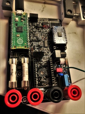
A Scope Test Tool You Can Build With Just A Pico

Ever wanted to see how well your oscilloscope adheres to its stated capabilities? What if you buy a new scope and need a quick way to test it lest one of its channels its broken, like [Paul Wasserman] had happen to him? Now you only need a Pi Pico and a few extra components to make a scope test board with a large variety of signals it can output, thanks to [Paul]’s Sig Gen Pi Pico firmware.

description of the signals generated by the software, that can be read in detail on the project websiteDespite the name it’s not a signal generator as we know it, as it’s not flexible in the signals it generates. Instead, it creates a dozen signals at more or less the same time — from square waves of various frequencies and duty cycles, to a PWM-driven DAC driving eight different waveforms, to Manchester-encoded data I2C/SPI/UART transfers for all your protocol decoder testing.

Everything is open source under the BSD 3-Clause license, and there’s even two PDFs with documentation and a user manual, not to mention the waveform screenshots for your own reference.

It’s seriously impressive how many features [Paul] has fit into a single firmware. Thanks to his work, whenever you have some test equipment in need of being tested, just grab your Pico and a few passive components.

Non Contact Scope Probe Costs Nearly Nothing

[IMSAI Guy] wants you to build a non-contact scope probe. The cost? Assuming you have a bit of wire and a regular scope probe, it won’t cost you anything. Why do you want such a thing? You can see what he does with it in the video below.

The probe is really just a coil with little slip-over coils that grab it. You can stick it on and remove it just as easily, so you don’t have to sacrifice the probe for normal use. It won’t give you high-accuracy readings, but if you want to sniff around a circuit without directly connecting to it, it will do the trick. If you are too lazy to make a coil, you can even clip a ground lead to the probe tip, although that won’t work quite as well.

Continue reading “Non Contact Scope Probe Costs Nearly Nothing”

80s Function Generator Is Both Beauty And Beast

You know how the saying goes — they don’t make them like this anymore. It’s arguably true of pretty much any electronic device given the way technology changes over time, though whether or not it’s objectively a bad thing is going to vary from case to case.

As a practical example, take a look at the insides of this 80’s vintage HP 3314A function generator shared on the EEV Blog Forum by [D Straney].

Hinged PCBs allow for easy access

With multiple PCBs stacked on top of each other, it’s hard to imagine that more components could possibly be crammed into it. One board in particular appears to be an entire Motorola 6800 computer, something which today would likely be replaced with a single microcontroller.

Which is actually why [D Straney] shared this with us in the first place. After seeing our recent post about a modern waveform generator that’s basically an empty box thanks to its modern components, they thought this would be a nice example of the opposite extreme.

So, is it a good or a bad thing that test equipment isn’t made this way anymore? Well, it’s hard to argue with the improved capabilities, smaller footprint, and reduced cost of most modern gear. But damn is the inside of this HP 3314A gorgeous. As one of the commenters on the page put it, hardware from this era was really a work of art.

Waveform Generator Teardown Is Nearly Empty

We always enjoy [Kerry Wong]’s insightful teardowns, and recently, he opened up a UTG1042X arbitrary waveform generator. Getting inside was a bit of a challenge since there were no visible screws. Turns out, they were under some stickers. We always dislike that because it is very difficult to get the unit to go back together.

Once open, the case reveals it is almost completely empty. The back panel has a power supply, and the front panel has all the working circuitry. The box seems to be for holding the foot and preventing the device from getting lost on your bench.

The power supply is unremarkable. There are a few odd output voltages. The main board is a bit more interesting, especially after removing the heat sink. There are two channels, but the board isn’t laid out, with a lot of segregation between the two channels. That makes sense with the output sections clustered together and the digital section with the CPU, FPGA, and the DAC in close proximity.

The other side of the board connects to a very simple display board. It would be interesting to compare this to a circa-1980s AWG, which would have been far more complicated.

Making a waveform generator with a microprocessor and a DAC isn’t hard. The hard part is the output stages and maximizing the operating speed.

Continue reading “Waveform Generator Teardown Is Nearly Empty”

Danish Vintage LRC Meter Reveals Inside

Modern test equipment is great, but there’s something about a big meter with a swinging needle and a mirror for parallax correction that makes a device look like real gear. [Thomas] shows us a Danish LCR meter (or, as it says on the front, an RLC meter). The device passes AC through the component and uses that to determine the value based on the setting of a range switch. It looks to be in great shape and passed some quick tests. Have a look at it in the video below.

An outward inspection shows few surprises, although there is an odd set of terminals on the back labeled DC bias. This allows you to provide a DC voltage in case you have a capacitor that behaves differently when the capacitor has a DC voltage across it. Continue reading “Danish Vintage LRC Meter Reveals Inside”

Tiny Signal Generator Revealed

There was a time when test equipment was big and heavy. Those days are gone, and [Kiss Analog] shows us the inside of a Uni-T UTG962E arbitrary waveform generator. The device is truly tiny. You might think this is due to the dense packing of the circuit board. However, one board is packed but the other board seems to have a high degree of integration on one IC. You can check out the video below.

The main processor is some sort of ARM — we think an STM32F-series part. The markings were hard to make out under the microscope.

Continue reading “Tiny Signal Generator Revealed”