This Kinetic Art Display Uses A Gin Bottle

[David McDaid] likes gin. So in homage to their favourite tipple, a certain brand of Scottish origin, a kinetic art project was brewed. Tabled as a Rube Goldberg machine — it’s not — but it is a very smart marble run type installation, dripping with 3D printed parts and a sprinkling of blinkenlights.

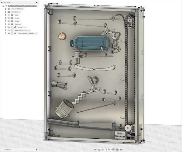
The write-up shows the degree of pain we go through with building such contraptions, apparently [David] burned through 2.5 kg of PLA filament despite the bill of materials requiring a mere 660 g. Much experimentation, trial and error, and plenty of print-and-reprint-until-good-enough, resulted in a clean looking run with some neat features. We particularly like the use of a stainless steel jigger to add a touch of metallic ting, to the soundscape produced. The whole show was put together in Fusion 360, since all those tight tolerances do not make for a simple construction without a lot of fiddling around with the layout. Once it was a sound, layout was prototyped on a wood board, which was subsequently used a drill template for the final acrylic version.

On the electronics side of things, an Arduino Nano clone is on control duty, reading an IR trip sensor to fire of a simple light effect, illuminating the gin bottle in a slick fashion. These machines need a mechanism to raise the balls against that pesky force of gravity, in this instance a 3D printed custom chain was constructed, driven with a stepper motor in turn driven from a TMC2208. You see, this thing lives in the kitchen, so the aim was to keep all the noise from the mechanics to a minimum so only the noise of LDPE balls rattling around can be heard. They are the star of the show after all! The build looks nice and would certainly be something we’d like to see on the wall. Obviously we’ve seen a few marble runs over the years. Here’s an interesting one that uses an elevator mechanism, and another project that shows how to generate runs procedurally.

Continue reading “This Kinetic Art Display Uses A Gin Bottle”

Burned Out SKR E3 Mini Gets New Stepper Driver

It didn’t take long to figure out that a dead X axis and an message saying “TMC CONNECTION ERROR” meant that one of the stepper drivers on the SKR E3 Mini 3D printer control board had released the magic smoke. Manufacturer BigTreeTech replaced the board under warranty, and the printer was back up and running in short order. But instead of tossing it in the trash, [Simon] wondered how hard it would be to repair the dead board.

Removing the original stepper driver IC.

The short answer is, not very hard. There was no question as to which of the four TMC2209 drivers was shot, since the X motor was the only one experiencing a problem. The drivers unfortunately aren’t socketed on this board, but after a little kiss with the hot air, the old chip was off.

[Simon] didn’t have any spare TMC2209 chips, but the TMC2208 has the same pinout and is a drop-in replacement. The TMC2208 is rated for a bit less current, but it shouldn’t be a problem under normal circumstances.

Other than the stepper connector getting a little toasty during the installation, the swap went off without a hitch and the board was up and running again. [Simon] ended up putting the now repaired SKR E3 Mini in his Ender 3; a nice 32-bit upgrade compared to the ATmega1284 that was originally running the show. Though in the past, he’s managed to squeeze a bit more performance out of the older 8-bit board as well.

Making A 3D Printed DSLR Camera Mount Even Better

We’d love to say that all of our projects worked perfectly on the first try, but the average Hackaday reader is a bit too experienced to buy a fib like that. The reality is, DIY projects rarely get everything right out of the gate. It takes some time to identify issues and work out all the kinks. But of course, that’s half the fun.

For a perfect example of this process, check out the latest update on the 3D printed DSLR camera mount that [isaac879] has been working on. When we last checked in with this project over the summer the mount was already impressive, but with the latest improvements and the addition of a whole new axis of movement, this homebrew camera motion system is an extremely compelling project for anyone who wants to take their project videos to the next level.

The new Hall effect sensor mounts are a very nice touch.

Back in June, the mount [isaac879] showed off was only capable of pan and tilt. But as you can see in the video after the break, he’s since mounted that to a track made of 20×40 aluminum extrusion and added another stepper motor. This allows the pan/tilt mount to move itself back and forth on the track to get those slick panning shots that all the cool kids use in their videos nowadays.

But even if you’re not interested in the slider aspect, the core pan/tilt mount has also received a number of refinements over the last few months. Perhaps the most obvious is the switch over to thinner and lighter stepper motors. Reducing mass is always an improvement with a moving system like this, and in the case of the pan motor, the shorter can prevents a potential collision with the camera itself. Obviously the smaller motors are weaker, but [isaac879] considers that a feature; the mini motors will just start skipping steps if things get bound up instead of potentially damaging your expensive camera.

He’s switched to flange bearings to help hold the frame together, improved wire routing, added a mounting point for the electronics, reprinted the pinion gears in a flexible filament to help absorb some vibrations, and switched over to TMC2208 stepper drivers. The new drivers may actually be one of the biggest usability upgrades, as they allow the entire mount to move faster and more accurately. Critically, [isaac879] also reports the new drivers have solved a troublesome vibration issue he was seeing when the camera was moving slowly.

Obviously you can throw together a simple pan and tilt mount with a couple of servos and some zip ties if you only need to use it once or twice, but a project of this caliber would rightfully become a permanent fixture in your workspace. Perfect if you’re looking to up your project photography game.

Continue reading “Making A 3D Printed DSLR Camera Mount Even Better”

A Little Rewiring Teaches A Creality Ender 3 New Tricks

The Creality Ender 3 is part of the new wave of budget 3D printers, available for less than $250 from many online retailers. For the money, it’s hard to complain about the machine, and it’s more than suitable for anyone looking to get make their first steps into the world of FDM printing. But there’s certainly room for improvement, and as [Simon] shows in a recent blog post, a little effort can go a long way towards pushing this entry-level printer to the next level.

The first step was to replace the printer’s stepper drivers with something a bit more modern. Normally the Ender 3 uses common A4988 drivers, but [Simon] wanted to replace them with newer Trinamic drivers that offer quieter operation. Luckily, Trinamic makes a drop-in replacement for the A4988 that makes installation relatively easy. You’ll need to change out a few caps and remove some resistors from the board to make everyone play nice, but that shouldn’t pose a challenge to anyone who knows their way around a soldering iron.

Beyond quieter running steppers, the Trinamic TMC2208 drivers also offer direct UART control mode. Of course the Ender’s board was never designed for this, so the MCU doesn’t have enough free pins to establish serial communications with the three drivers (for the X, Y, and Z axes). But [Simon] realized if he sacrificed the SD card slot on the board, the six pins that would free on the controller could be cut and rewired to the driver’s UART pins.

Combined with the Klipper firmware, these relatively minor modifications allows him to experiment with printing at speeds far greater than what was possible before. Considering the kind of headaches that a ~$200 printer would have given you only a few years ago, it’s impressive what these new machines are capable of; even if it takes a few tweaks.